Hello
I'm planning to build a subwoofer consisting of Peerless 12" XLS driver and Peerless 12" passive radiator. These will be placed in ~40litre box. Now I'm not sure about some things and I hope you guys could clear them out for me. Firstly are drivers meant for cars any good for home systems? That 4ohm nominal impedance would be great since I'm also building the amplifier myself. Since this is my first DIY audio project I'll probably start with easier amp (gainclone PA100 with LM3886 chips) but I need some facts will this be powerfull enough for driving this subwoofer at 8ohm load or should I buy the car version instead.. or go for bigger amp?
As for the amp, things I'm looking for are regulated psu, adjustable low-pass filter (I'll probably try Elliot's '
Eight Band Sub-Woofer Graphic Equaliser'), a subsonic filter, driver protection and volume control but more about this later. Have to decide the amp first")
Thanks for your time and sorry about my messy english. Still learning
I'm planning to build a subwoofer consisting of Peerless 12" XLS driver and Peerless 12" passive radiator. These will be placed in ~40litre box. Now I'm not sure about some things and I hope you guys could clear them out for me. Firstly are drivers meant for cars any good for home systems? That 4ohm nominal impedance would be great since I'm also building the amplifier myself. Since this is my first DIY audio project I'll probably start with easier amp (gainclone PA100 with LM3886 chips) but I need some facts will this be powerfull enough for driving this subwoofer at 8ohm load or should I buy the car version instead.. or go for bigger amp?
As for the amp, things I'm looking for are regulated psu, adjustable low-pass filter (I'll probably try Elliot's '
Eight Band Sub-Woofer Graphic Equaliser'), a subsonic filter, driver protection and volume control but more about this later. Have to decide the amp first
Thanks for your time and sorry about my messy english. Still learning
I would say go with the 4 ohm subwoofer, because you can parallel either two lm3886's or two 3875's to get about 100 watts. With 8 ohms, you're only looking at about 50 watts, unless you bridge the chips. You may even want to see if you can find a 2 ohm subwoofer (or dual 4 ohm voice coils), that way you could parallel 4 lm3875's for about 200 watts.
Hi provio,
I don't know if you have already read this site, but if you don't have a look:
http://linkwitzlab.com/thor-intro.htm
It's describing a subwoofer with the driver you want and it also explains lot of things. I Have used it to calculate the power needed for my subs.
I don't know if you have already read this site, but if you don't have a look:
http://linkwitzlab.com/thor-intro.htm
It's describing a subwoofer with the driver you want and it also explains lot of things. I Have used it to calculate the power needed for my subs.
Hi again
Thanks for your suggestions and for the link yesgrey3, it seems to be informative.
I will probably go with 8ohm version since I have never heard a subwoofer designed for car's cabin being used in bigger room and because
the T/S parameters betweed these 2 drivers depart from each other (I would probably have to use bigger box with the car driver) and also because
of the price of course. I also decided to use NIGC BPA200 with DC-servo for driving the sub. I know that size isn't straightly comparable with better
sound quality and that I should start with simple GC but what the heck, I like the challenge
I started designing the amp on the base of AN-1192. Is it ok as it is or is there something (critical) that I should take notice of? Should I use snubbers?
Is ±30V rail voltage ok or should I use ±35V? Will 500VA transformer do the job?
I haven't found LF411ACN/LF412ACN op amps from local electronic shops (yet), so I thought of using LF411CN/LF412CN instead. Are these suitable for
the job or should I use some other chips? The datasheets give the A-versions a supply voltage value of ±22V and ±18V for normal ones.
I presume these are minumum values and I could power the chips with my rail voltage? Or do I need another psu?
I'm also having troubles finding 1N456A diodes used in the DC-servo circuit. What whould be a good low-leakage diode for replacement?
Thanks for taking your time to answer these basic questions. I appreciate your help.
Thanks for your suggestions and for the link yesgrey3, it seems to be informative.
I will probably go with 8ohm version since I have never heard a subwoofer designed for car's cabin being used in bigger room and because
the T/S parameters betweed these 2 drivers depart from each other (I would probably have to use bigger box with the car driver) and also because
of the price of course.
I also decided to use NIGC BPA200 with DC-servo for driving the sub. I know that size isn't straightly comparable with better sound quality and that I should start with simple GC but what the heck, I like the challenge
I started designing the amp on the base of AN-1192. Is it ok as it is or is there something (critical) that I should take notice of? Should I use snubbers?
Is ±30V rail voltage ok or should I use ±35V? Will 500VA transformer do the job?
I haven't found LF411ACN/LF412ACN op amps from local electronic shops (yet), so I thought of using LF411CN/LF412CN instead. Are these suitable for
the job or should I use some other chips? The datasheets give the A-versions a supply voltage value of ±22V and ±18V for normal ones.
I presume these are minumum values and I could power the chips with my rail voltage? Or do I need another psu?
I'm also having troubles finding 1N456A diodes used in the DC-servo circuit. What whould be a good low-leakage diode for replacement?
Thanks for taking your time to answer these basic questions. I appreciate your help.
No, these are maximum values. You will need to provide a separate power supply for the opamps. The most common voltage to use is +/- 15 V. You can use a couple of simple 3-terminal regulators to regulate your amp rails down to +/- 15V for the opamps (see "U8" and "U9" in AN-1192; did you overlook that?). The non-"A" version of the opamps will work just fine.The datasheets give the A-versions a supply voltage value of ±22V and ±18V for normal ones.
I presume these are minumum values and I could power the chips with my rail voltage? Or do I need another psu?
For an 8 ohm load, go for +/- 35 V rails. That is just about the ideal voltage to maximize output power into 8 ohms. 500 VA will do just fine; even 300 VA or so would be adequate. Don't forget that when choosing a transformer, the AC voltage must be 71% of the desired DC voltage. So for +/- 35 VDC rails, you need a transformer with either dual 24 VAC to 25 VAC outputs, or a single 48 VAC to 50 VAC centre-tapped (often called simply "50 VCT") output. Dual secondaries give you more flexibility in how you build your power supply, since you can wire them up to be centre-tapped or leave them separate or even parallel them (if you only need one output not two).Is ±30V rail voltage ok or should I use ±35V? Will 500VA transformer do the job?
macboy said:
No, these are maximum values. You will need to provide a separate power supply for the opamps. The most common voltage to use is +/- 15 V. You can use a couple of simple 3-terminal regulators to regulate your amp rails down to +/- 15V for the opamps (see "U8" and "U9" in AN-1192; did you overlook that?).
Yup I somehow missed that part. Thanks for clearing this out.
macboy said:
Don't forget that when choosing a transformer, the AC voltage must be 71% of the desired DC voltage. So for +/- 35 VDC rails, you need a transformer with either dual 24 VAC to 25 VAC outputs, or a single 48 VAC to 50 VAC
I'm going to use linear regulators so do I need to worry about AC output, as LM338 is capable of "+40V, -0.3V input/output differential"? If my VDC secondaries are 38Vrms, I could theoretically drop the voltage to 15V with these chips right? Although that could get a little

If my VDC secondaries are 38Vrms, I could theoretically drop the voltage to 15V with these chips right? Although that could get a little
That's right and you are closer to the ice cap than me so don't add to the global warming!
I wouldn't want to drop more than 10 volts through the LM338 unless you use some serious heatsinks! 
bpa200 in national application note both uses inverted and non-inverted configurations. Instead of having 2 different configurations driven by the same signal, you can drive symetrically and use only 1 configuration. Example: signal to first NIGC and inverted signal to second NIGC. It's simpler (parts selection, same PCB for both legs of bridge), probably better, and surely easier to set up.provio said:I also decided to use NIGC BPA200 with DC-servo for driving the sub.
LF412 is ok for the DC-servo. For the buffer, you can use whatever opamp you like: opa2134, OP275, etc...I haven't found LF411ACN/LF412ACN op amps from local electronic shops (yet), so I thought of using LF411CN/LF412CN instead. Are these suitable for
the job or should I use some other chips?
From my experience, 1n4148 is a good starter for the job. I've read that one of the best low leakage diode is...a cheap transistor! Simply take a low cost NPN transistor, and tie base to collector.I'm also having troubles finding 1N456A diodes used in the DC-servo circuit. What whould be a good low-leakage diode for replacement?
Alas, I learned this trick after having bought a bunch of low leakage diodes bas45a.
Thanks for taking your time to answer these basic questions. I appreciate your help. [/B][/QUOTE]
Ah, but don't forget that the only thing that these regs are powering is a couple opamps, not the power amps. With only a few mA of current flowing through them, you can easily drop the voltage 10 V or 20 V or 30 V and still probably get away with using no heatsinks at all! I rarely use heatsinks on my pre-amp regulators, and even sometimes use those little TO-92 case, 100 mA regulators (e.g. 78L12).Nuuk said:... I wouldn't want to drop more than 10 volts through the LM338 unless you use some serious heatsinks!
Ah, but don't forget that the only thing that these regs are powering is a couple opamps, not the power amps.
Yes you are right. I thought they were for powering the power amp chips. I don't use heatsinks on any of my pre-amp/buffer regs either!
macboy said:
Ah, but don't forget that the only thing that these regs are powering is a couple opamps, not the power amps.
This is getting a little confusing
I meant to use LM338s for regulating the whole amp, LM3886s included. I would then use LM7xL15s to drop the voltage from ±35V rails for opamps. Is this even reasonable or should I just build normal unregulated PSU?
About snubbers, is the resistor+capacitor combo supposed to be placed before capacitors between V+/- and GND? What about between V+ and V-? Is there any good schematic or picture showing how this should be done?
No, it is not resonable to expect a single pair of 5 A regulators to power four LM3886's. If you used a pair of regulators per LM3886, that would work. But why? Regulated supplies are (IMHO) overrated, and in this specific case, where you are building a subwoofer amp, they are totally and completely unnecessary. The only function they could serve is as space heaters. Save your money.provio said:This is getting a little confusing
I meant to use LM338s for regulating the whole amp, LM3886s included. I would then use LM7xL15s to drop the voltage from ±35V rails for opamps. Is this even reasonable or should I just build normal unregulated PSU?
(Consider this as an intellectual exercise - the regulators can handle up to 5 A, so if you were able to use them at that maximum level, the maximum current through your 4 ohm load is 5 A. The RMS current will be 3.54 A (for a sinewave). Then RMS Power, P = I^2 * R = 50 W. So with a single pair LM338's regulating your power supply rails, the maximum power you can get out of any amp of any topology is 50 W RMS (into 4 ohms). This is a limit imposed by your power supply. If you use really big caps on the output of the regulators to smooth out the current requirements from the regulators, you may be able to get 5 A average (or RMS) out of them. Then power would be 100 W in to 4 ohms, but that's really stretching it. And that's assuming that you do not have to derate the output current capability of the regulators for any reason, including Vin - Vout being too high, excessive temperature due to inadequate heatsinking, etc.)
macboy said:
No, it is not resonable to expect a single pair of 5 A regulators to power four LM3886's.
Yes I was actually thinking of using 2 or more regs per rail. This would still probably be cheaper than buying 80000uF worth of capacitors.
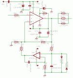
Here (in the attached image) is part of my schematic which is based on AN-1192. What do you guys think, is there something I should change? Would 0,09R be better than 0,11R for Ro? Should I use capacitors at LF412N's suppy pins?
If I will use carlosfm's unregulated PSU design, is it ok to just add 20000uF per rail or should I change something else?
Attachments
provio said:Hello
I'm planning to build a subwoofer consisting of Peerless 12" XLS driver and Peerless 12" passive radiator. These will be placed in ~40litre box. Now I'm not sure about some things and I hope you guys could clear them out for me. Firstly are drivers meant for cars any good for home systems? That 4ohm nominal impedance would be great since I'm also building the amplifier myself. Since this is my first DIY audio project I'll probably start with easier amp (gainclone PA100 with LM3886 chips) but I need some facts will this be powerfull enough for driving this subwoofer at 8ohm load or should I buy the car version instead.. or go for bigger amp?
As for the amp, things I'm looking for are regulated psu, adjustable low-pass filter (I'll probably try Elliot's '
Eight Band Sub-Woofer Graphic Equaliser'), a subsonic filter, driver protection and volume control but more about this later. Have to decide the amp first
Thanks for your time and sorry about my messy english. Still learning
You can also consider the OPA549 or 541 in parallel-bridge using 4 ohm driver. If you can get it for samples then that would be a good start. i fried lot of chip amps before making one work
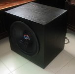
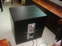
here is my sub using a OPA 549 in para-bridge with Rod elliot's EAS filter and a cheap 15" car subwoofer.
Attachments
OPA541 Design
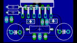
Hello all, I have also been thinking about putting together a sub amp to replace y current underpowered unit. My plan is to use a pair of bridged non-inverted OPA541's. The bridging will be accomplished with a DRV134 similar to Digi's design. I have attached my first draft of a PCB. The plan is to use two of these and mount the bridging board in between. Obviously the caps on board are a bit small for a sub, there will be a pair of 6800uF caps on the PSU board. I'm going to try unregulated first as I would like to keep it as simple as possible. I really don't need a filter of any sort as I am using this with an HT preamp that has a sub out, If I do add one I'll likely just use an adjustable active lowpass filter with an OPA134...cheap and simple.
G.
Attachments
- Status
- This old topic is closed. If you want to reopen this topic, contact a moderator using the "Report Post" button.
- Home
- Amplifiers
- Chip Amps
- Gainclone for subwoofer