In an earlier post by Carlos he showed some pictures of a grounding scheme he was using with some BrianGT boards. However I can't seem to find it even though I searched for it. Aslo I'm not sure I completely understood it. Is the attached picture an accurate depiction of waht Carlos was suggesting?
Attachments
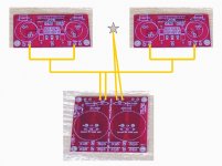
It's been posted here: http://www.diyaudio.com/forums/showthread.php?postid=617246#post617246 and it works well, especially with LM4780 boards powered from a common supply.
kestrel200 said:Is the attached picture an accurate depiction of waht Carlos was suggesting?
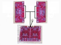
Yes, sorta.
Corrected.

Attachments
Re: Re: Carlos grounding Scheme
Thanks Carlos!!!!! It's clear now! I was confused about the what you did with the extra pair of the power supply's PG+ & PG- but I see you just leave them empty.
Thx again!
carlosfm said:
Yes, sorta.
Corrected.
Thanks Carlos!!!!! It's clear now! I was confused about the what you did with the extra pair of the power supply's PG+ & PG- but I see you just leave them empty.
Thx again!
Peter Daniel said:It's been posted here: http://www.diyaudio.com/forums/showthread.php?postid=617246#post617246 and it works well, especially with LM4780 boards powered from a common supply.
I guess this is a question for Carlos -- what is the wire you use for the ground wires. I see that it is thick copper, but is it just stripped solid core wire, or is there some other source for it?
-d
Upupa Epops said:By this method of grounding exist theoreticaly little crosstalk between channels, 'cos any ground wire have zero resistance.
I do not understand. You probably mean that no ground wire has zero impedance.
 .
.dsavitsk said:I guess this is a question for Carlos -- what is the wire you use for the ground wires. I see that it is thick copper, but is it just stripped solid core wire, or is there some other source for it?
On the chip boards you can fit 1.5mm solid core copper.
Get those boards close from each other.
Then use a thick solid core wire (1.5~2.5mm) to join the two boards.
Coming from the PSU to the center of that wire I use multi-strand 2.5mm copper.
This is all normal electrical wire, no need to get fancy.

Upupa Epops said:By this method of grounding exist theoreticaly little crosstalk between channels, 'cos any ground wire have zero resistance.
Nothing to worry about.
Yes, it's a common PSU for two channels.
Even then, it's still better than using a single LM4780 chip for stereo.
")
It is also the way to make a silent amp, no hum.
I have been explaining this for years... glad that someone had the brilliant idea to make a sketch.

Another way, which I think is more elegant, is to connect two amp boards OG (output ground) points with a thick wire. Then run both ground returns separately (from a single rectifiers board) to a central point on that wire.
It produces hum free results.
As to the boards designed the way they are, they were optimized for dual mono setup, and they work fine this way.
It produces hum free results.
As to the boards designed the way they are, they were optimized for dual mono setup, and they work fine this way.
carlosfm said:
On the chip boards you can fit 1.5mm solid core copper.
Get those boards close from each other.
Then use a thick solid core wire (1.5~2.5mm) to join the two boards.
Coming from the PSU to the center of that wire I use multi-strand 2.5mm copper.
This is all normal electrical wire, no need to get fancy.
Carlos,
How important of the chassis ground it is? Just wonder what if we leave it out (e.g. in case of wooden chasis).
PS: Your snubberized PS sound great!
Thanks.
Upupa Epops said:Carlos, if you will lead both ground wires separate to the middle between elyts, it will be quite the same silent, but there will be not crosstalk. Do you understand, where is problem of your solution ?
That way it will be silent, yes, IF the PSU is right between the two channels and those wires are very short.
There are several ways to do the same thing.
Placing the chassis ground right between the two channels and connecting everything there would also do.
What I describe for grounding gives you more freedom to where you place the PSU.
This way it can even be external and you still have a silent amp.
methar said:How important of the chassis ground it is? Just wonder what if we leave it out (e.g. in case of wooden chasis).
Chassis ground is for shielding.
If you will have problems without it may depend on where you live.
Strong radio transmissions nearby, radars...
Anyway, these days with mobile phones and everything without wires, RF pollution is high.
I don't have problems even testing an amp without a chassis, but some have.
Try it on a wooden chassis. If you have problems you can shield it inside with aluminium or copper tape.
Carlos, I mean, that you don't understand me. Correct ground plan haven't common ground wire between both two channels and PS. Correct grounding have two separate ground wires from PA to PS, which both must be connected to the geometrical middle between both elyts. Only in this case you have not ( theoretically ) crosstalk.
Peter Daniel said:Another way, which I think is more elegant, is to connect two amp boards OG (output ground) points with a thick wire. Then run both ground returns separately (from a single rectifiers board) to a central point on that wire.
It produces hum free results.
As to the boards designed the way they are, they were optimized for dual mono setup, and they work fine this way.
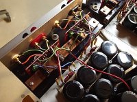
I do mine slightly different. It is hum free for me see the two green wires I made sure they are as close to exactly length as possible. The location of the angar point does not matter, but if the length are not the same may have noise. The red wire is the Earth. Sorry I have no chassis for it to ground yet.
Attachments
Upupa Epops said:Carlos, I mean, that you don't understand me. Correct ground plan haven't common ground wire between both two channels and PS. Correct grounding have two separate ground wires from PA to PS, which both must be connected to the geometrical middle between both elyts. Only in this case you have not ( theoretically ) crosstalk.
Theoretically, but not in practice.
Yes, I understand you.
Well, how do you make that for an external PSU?
You would have two separate long wires to the main PSU caps?
Hum for sure.
I repeat: you can do that with an on-board PSU, placed as close as possible to the amp modules. Preferably in the middle of them.
There are advantages in having off-board PSU, as there are advantages in having everything integrated.
I prefer off-board, most of the times that's what I do.
- Status
- This old topic is closed. If you want to reopen this topic, contact a moderator using the "Report Post" button.
- Home
- Amplifiers
- Chip Amps
- Carlos grounding Scheme