Hello Just after peoples impressions on the LM1875 design from silicon chip personally I think it could be a lot smaller in design than it is, but they say it works ok the reason I am asking for your impressions is I wish to make a few of these LM1875 amps and just stumbled across the Silicon chip design and thought I would post here for feedback.
Thankyou any help much appreciated
Cheers
AB
P.S. here is the link for the amp
http://www.siliconchip.com.au/cms/A_103236/article.html
Thankyou any help much appreciated
Cheers
AB
P.S. here is the link for the amp
http://www.siliconchip.com.au/cms/A_103236/article.html
I made a few 1875 modules to power my main amp a few years ago, and basically followed the data sheet. I built mine (5 channels) on individual bits of veroboard with no hassles.
In my opinion (which has been influenced by ears that are not golden....) they sound great.
The volume control doesn't go past half way.
I've also built an LM3886 amp that also sounds just fine, also on veroboard. It's in use as a "loud" amp when my wife has a singing session.
I've never put the two head to head to try to compare the sound of them, because (a)I couldn't be bothered, and (b)because I've been suitably amazed with both of them for their simplicity, their ease of use, and their lack of noise.
If you want simple, and it's only for the lounge room, go for the LM1875. With only five pins, it's hard to stuff it up. Just make sure you have a nice power supply reserve behind it, something like CarlosFM's "snubberised" setup, and you'll be fine.
Having said all that, I'm going to re-do my amp with some 3886s one day. That will be after I make the 200w "louder" amp with 6x 3886s for PA use....
Too many projects, not enough time...
Paul.
Rod Elliott's ESP site does a 1875 circuit
board and it is more compact and has
two amps on it. That is if you want a readily
available 1875 low hassle option and are
not going for a hardwire attempt.
http://sound.westhost.com/project72.ht
Regards
AnthonyPT
board and it is more compact and has
two amps on it. That is if you want a readily
available 1875 low hassle option and are
not going for a hardwire attempt.
http://sound.westhost.com/project72.ht
Regards
AnthonyPT
Hello everyone thanks for all your replys much appreciated I got given 10 of these lm1875 chips from a friend at a electronics shop that has now closed thought I would put them to good use and yes NITRO I would love to have a look at your lm1875 design if thats ok please e-mail when you get a chance
Thanks again everyone for your feedback
Regards
AB
Thanks again everyone for your feedback
Regards
AB
paulmac said:If you want simple, and it's only for the lounge room, go for the LM1875. With only five pins, it's hard to stuff it up. Just make sure you have a nice power supply reserve behind it, something like CarlosFM's "snubberised" setup, and you'll be fine.
I always liked the LM1875 very much.
That's what I use on my bench, always listening to it.
LM1875 + snubberized PSU.
I have tested this amp on my main system, with my difficult Epos ES11 speakers and I could not believe... it drives them quite well.

Also, it's small, I can take it everywhere.
It made quite a success on this year's new year's day party, with an old Philips portable multibit CDP (tweaked) and a pair of (tweaked) Boston speakers I have.

Who wants to make a small, simple amp should try these chips.
Beware, you can end up with a (low power) high-end amp.
Hi Angel-Baby,
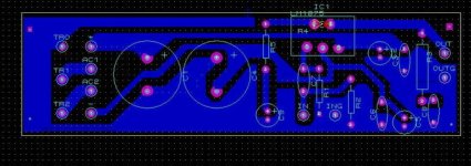
Here's my PCB layout for lm1875,i hope you'll like it.By the way there's one important point on layout.There's one hard to see SMD resistor between IC pins 4 and 2 as a feedback/gain resistor that directly soldered to pins.But if you don't have any SMD you can use conventional resistor in the same place because there is a enough space in that area.
Here's my PCB layout for lm1875,i hope you'll like it.By the way there's one important point on layout.There's one hard to see SMD resistor between IC pins 4 and 2 as a feedback/gain resistor that directly soldered to pins.But if you don't have any SMD you can use conventional resistor in the same place because there is a enough space in that area.
Attachments
Carlos, what schematic is your LM1875 amp based on?I always liked the LM1875 very much.
That's what I use on my bench, always listening to it.
LM1875 + snubberized PSU.
I am building an amp with LM1875s and I'd like to get the best sound quality possible. I've made one some time ago using the data sheet's schematic, but I guess there's a better way.
Regards,
Michal.
Application Hints
STABILITY
The LM1875 is designed to be stable when operated at a
closed-loop gain of 10 or greater, but, as with any other
high-current amplifier, the LM1875 can be made to oscillate
under certain conditions. These usually involve printed circuit
board layout or output/input coupling.
carlosfm is banned and will not answer
For a lower supply like +-15V a gain of 10 would be good
Around 1 Vrms input would give maximum power peaks.
For schematic the recommended standard circuit from National datasheet would work best.
Reason?
Because National want their chips to work good and become popular
So, if they would NOT publish optimal standard circuit,
they would not act in there own interest of selling many chips.
Customers staisfied = Best advertising
We should not have any doubts, that this standard circuit has been carefully tested
in very advanced electronical laboratory with test personel with high education/knowledge
and that have testing gears we DIY members can only dream of
Such a big company as world leading National Semiconductors
does not pick amateurs of the streeet when selecting their technical staff.
They can afford to handpick only the best.
This is why you should FIRST consider the standard circut.
From this you can make small adjustments, if your system have some special need.
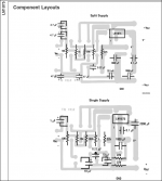
Also for PCB study the recommended PCB layout for LM1875.
It is not done by chance by some unqualified personand not without careful consideration and testing
Let us not fool our selves too much, in thinking we know better than best qualified people.
After all, they do this for their profession. With the experience that comes from years.
-------------------------
Some DIY members here are good.
But I do not for one minute think
that National handpicked laboratory personel is inferior in any aspect of Audio electronics.
Links:
http://www.national.com/ds/LM/LM1875.pdf
Search www.diyaudio.com for LM1875, via google:
http://www.google.com/search?q=+site:diyaudio.com+diyaudio+LM1875
Attachment.
LM1875 PCB layout.
note: Should be mirrored, as is shown from component side.
Attachments
Small layout is good, especially when you're making hundreds of thousands it can reduce cost, but for a hobbyist there can be other concerns and small size really does not matter if you have a ground plane. Remember that besides the feedback loop, or power rail decoupling, other signal path distances are already going across wires many times as long as a centimeter saved or lost.
I've not made an LM1875 but I did a couple LM4752 builds as cheaply as possible out of spare parts and found what worked best for me was using the project cases I had, the scrap heatsinks I had mounted on the board itself, making the board sized to fit the whole project case so there was a board mounted power switch and LED in front,and have jacks mounted on the rear of the board. On second thought maybe the LED was on wires still, it has been a long time since I built it.
I've not made an LM1875 but I did a couple LM4752 builds as cheaply as possible out of spare parts and found what worked best for me was using the project cases I had, the scrap heatsinks I had mounted on the board itself, making the board sized to fit the whole project case so there was a board mounted power switch and LED in front,and have jacks mounted on the rear of the board. On second thought maybe the LED was on wires still, it has been a long time since I built it.
- Status
- This old topic is closed. If you want to reopen this topic, contact a moderator using the "Report Post" button.
- Home
- Amplifiers
- Chip Amps
- LM1875 from Silicon Chip Your Impressions