Only for the little that go across the border inverting OPamp and non- inverting, my complete cookies.
This configurations don't see easily in the forum, because anyone has the abilities to develop usually uses it for money. I hope that some is able draw an advantage. The draw is 2 schemes. Schemes first are a circuit that I have built "the flight" to do some test, and I have thought that were able be of interest to some beginner. In practice this is an OPamp shaped in Tracking, or in degree to develop a range of tension in exit much more tall, on account of the V power floting. The second circuit is that more original. Trade of a Power current/current converter, that is it may use as buffer (unit gain) for audio circuits to ample swing. if it connects directly, without insert it in the negative feedback , himself you produce a "Stasis" amplifier. This technique has been invented and patented by Nelson Pass, and second-hand commercially. In practice, this special type of buffer "sense" the current to the load from the amplifier of tension, and from it amplifies the value, but without influence on the performances. If they use this buffer with preampli to valves to ample swing, or to discrete in class A to the results can be exceptional. For a fast evaluation, it may use the Tracking circuit enclosure. To do it works at the best the buffer, suggestion to using a Voltage amp. with Zout<10 ohms and output current +-50mA. the more experts are able modify the parameters of the buffer using the formulae take root. I hope that some does a favor to publish to forum a " Hi-end "drive circuit. I creed to have done broadly my part, and withdraw me.
Ciao and good work
Mauro Penasa
Attachments
mauro, i think its really amazing that you contribute this completely new and radical implimentations of the national chips. i just wish i had close to enough understanding to even be able to understand what you're talking about.
maybe your ideas will eventually trickle down into future PCB kits that i could understand a little better.
thanks mauro.
maybe your ideas will eventually trickle down into future PCB kits that i could understand a little better.
thanks mauro.
It looks great Mauro!!! Stasis always sounds interesting and intriguing to me but have not built anything similar to have an opinion on it.
Would love to see others follow this road and maybe some PCB for the circuit and I might give it a try.
Did not quite understand what you said regarding the buffer and the use of a pre with this circuit, could you explain in other words?
Cheers….
Would love to see others follow this road and maybe some PCB for the circuit and I might give it a try.
Did not quite understand what you said regarding the buffer and the use of a pre with this circuit, could you explain in other words?
Cheers….
Hi, Mauro,
Nice designs
Sorry, I still dont get it. Which patent? Or which Statis does it related to?
Nice designs
This technique has been invented and patented by Nelson Pass
Sorry, I still dont get it. Which patent? Or which Statis does it related to?
maupenas, good idea but LM3875 can't be used for this purpose because it isn't stable for gains less than 10. Have you tested your idea in real life?
The voltage gain maybe 1 (voltage buffer). But the current gain in right schematic is 100/0.1ohm=1000x. Is this making chipamp unstable?
Does this kind of "Current Amplifier" suitable for driving ordinary speakers (which is designed for voltage source amplifiers)?
Various precise statements:
The "stasis" brevet is operational after 1978 and is in use by Threshold.
My scheme has not commercial intentions and then it is can make a will.
Datum that the "Stasis" idea is not mine, and it is broadly divulged by Pass, not time perderoes to describe it in the detail. The circuit that I have proposeded is not a "normal" buffer to unit gain voltage, but a current/current converter with input connected directly to the exit.
the Voltage amplifier that it connects to the input furnishes a tide directly to the load, but for effect of the bridge it "sees" a load with 1000 times + tall (our case) in comparison with that reality.
Datum that the circuit of tide is external a the Neg. feedback of the voltage driver amplifier, produces to all the effects the "stasis" mechanism ( is not a hypothesis,it is a certainty ). If they measure the distortion of the circuit discover that is equivalent perfectly to that of the Voltage stadium. The fact that Threshold has always used this technique with "current mirrors" and with discrete components, change the medium. If then some shows me that get it same effects of "Stasis" without respect from it the parameters, means that have invented a new system and I am able patent it.
I don't know other applications as this ( Threshold to depart ) but even for effect of the brevet, I doubt that other builders have used it.
For what concerns the doubts concern to the stability, for fortune sees that some expert takes part in explain ( better than my)
the dynamics of operation. I never don't expose circuits that doesn't work well, because this circuits have been make a will in laboratory on real prototypes. If have good bases of electronics, discover that my nets never are not banal, and itis able help you even for Your projects. in this particular case, the stability is guaranteed by R8 and C1, that I am not optional, but it creates of the pole/zero conjugated with the rest of the bridge and make it stable. this technique is second-hand ( a few ) to stabilize "on external" the no-compensateds OPamp, as LM3875 and LM3886 ( still more unstable ) and the point of work is calibrated on the prototype.
For the beginners:
For Voltage stadium I intend an amplifier to discrete or OPamp that produces the necessary voltage-gain to drive the loudspeakers ( es. 1Vin > 20Vout). If they connect my buffer to your pre-amplifier, works all well but they don't succeed to have a greater power of 5-10W. to get an amplifier in "stasis" has to build an pre-amplifier In degree to produce a voltage swing about 30Vpp and Zout<10ohm, capable of output current furnish with at least 20-50mA.
It may use a tracking circuit as what I have proposeded or other technology, as the valves circuits, or the Mosfet circuits of Pass. The output distortion and the general sound are that of the driver.
Ciao
Mauro
Hi Mauro,
Very interesting and ingeneous ideas! I think that in pratice there may be some brawbacks, like:
- power wasted in the current sense resistor;
- the need for a differential input (the input R is between inputs and not between an input and gnd). Of course, you may wan t to use diff input signal.
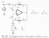
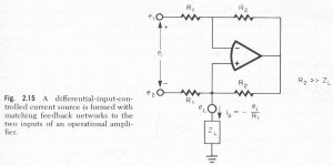
Just to give you some - admittedly VERY basic ideas - I attach two schemes that get around this. They are from "Designing with opamps - application alternatives", by the former BB lead designer Gerald Greame.
Jan Didden
Very interesting and ingeneous ideas! I think that in pratice there may be some brawbacks, like:
- power wasted in the current sense resistor;
- the need for a differential input (the input R is between inputs and not between an input and gnd). Of course, you may wan t to use diff input signal.
Just to give you some - admittedly VERY basic ideas - I attach two schemes that get around this. They are from "Designing with opamps - application alternatives", by the former BB lead designer Gerald Greame.
Jan Didden
Attachments
... and the other one:
BTW, There was some comment above on the stability. The LM3886 may not be the best one as is it is not unity-gain compensated - I see some signs of those potential problems in your compensation networks! I don't know a better alternative but it may be useful to look around to get the best GBW available.
Jan Didden
Attachments
Hi, Mauro,
Is it "Statis" like in the term of sliding class G in left schematic? Or is it "Aleph" because the right schematic has R in the output?
I've seen the left schematic used in commercial headphone amp (I don't remember the brand, but it is headphone amp, multichannel, using opamp with boosted output like your left schematic, using +/-30V supply, sliding in range of +/-15V, usually used by musicians in studio recordings).
But the right schematic. I've never seen it and it's smart
Is it "Statis" like in the term of sliding class G in left schematic? Or is it "Aleph" because the right schematic has R in the output?
I don't know other applications as this ( Threshold to depart ) but even for effect of the brevet, I doubt that other builders have used it.
I've seen the left schematic used in commercial headphone amp (I don't remember the brand, but it is headphone amp, multichannel, using opamp with boosted output like your left schematic, using +/-30V supply, sliding in range of +/-15V, usually used by musicians in studio recordings).
But the right schematic. I've never seen it and it's smart
Not I went to school in founding the circuits that show me, but I think that the problem of the dissipation of the power on the "sense" resistor remains ( R2 in the schemes ) and this configurations are a lot of difficult by stabilize on LM3886. In more, with the bridge that I have chosen, I prepare of a differential entry ( on R6 ) and of the "floating" exit that is able connect to any "reference".
LM3886: he is hard to please to compensate, and true. But I the have done. We are able argue much on our choices, but I am a lot of pragmatic: This circuit you allows to study the stasis technical using your preferred VAS, and works perfectly. If they use a VAS with 0.00001% THD, to the output, on the load, you will have that value, and the THD of my bridge comes annuled. Is a lot of useful to analyse the limits of my buffer or is better think to a reference VAS ?
Your contribution to the discussion is always well accept.
Mauro
Mauro
Thanks for your great inputs in this forum!
I am not an EE and still try to understand your suggestion in detail.
Is it like this: I could use a triode in front of this circuit as voltage gain circuit and then connect your circuit for current amplifying?
Kind regards
Franz
Thanks for your great inputs in this forum!
I am not an EE and still try to understand your suggestion in detail.
Is it like this: I could use a triode in front of this circuit as voltage gain circuit and then connect your circuit for current amplifying?
Kind regards
Franz
maupenas said:Not I went to school in founding the circuits that show me, but I think that the problem of the dissipation of the power on the "sense" resistor remains ( R2 in the schemes ) and this configurations are a lot of difficult by stabilize on LM3886. In more, with the bridge that I have chosen, I prepare of a differential entry ( on R6 ) and of the "floating" exit that is able connect to any "reference".
LM3886: he is hard to please to compensate, and true. But I the have done. We are able argue much on our choices, but I am a lot of pragmatic: This circuit you allows to study the stasis technical using your preferred VAS, and works perfectly. If they use a VAS with 0.00001% THD, to the output, on the load, you will have that value, and the THD of my bridge comes annuled. Is a lot of useful to analyse the limits of my buffer or is better think to a reference VAS ?
Your contribution to the discussion is always well accept.
Mauro
Mauro,
You are right, also in the basic schemes the problem of dissipation in the "sense" resistors remains and is even larger than in your case, I overlooked that.
I think I understand your reasoning on the "annuling" (cancellation?) of the THD, but wouldn't that require precises ratio's between the various feedback resistors in your output stage?
Jan Didden
Franz_G: If you connect a VAS ( Voltage Gain Stage ) to triodes ( or any other technology ) capable of a output current max. about 20-50mA, and with output impedance of 10-50max ohm, you are able a driver directly a loudspeaker, within the power target of LM3875 or LM3886. The advantage of this circuit respect to a normal power buffer ( Unit voltage gain) is in the fact that the THD ( already little ) of the buffer comes checked nearly totally from your VAS, without need to insert a global NFB (negative Feedback). This solution believes that is the more "genial" among that proposed by Pass, because is a lot of flexible.
Ciao
Mauro
Ciao
Mauro
Janneman: The yours are good questions. As I have already said in other thread, my translations in English is very bad, and I do labours to express clearly my concepts. I hope that you understand at least the principal things.
"sense resistors": to clarify, my circuit has 2 "current sensing resistors ", one of power (R5) that is directly on the load ( and dissipates a discreet power ) and one of signal (R6) that is fundamental but it has only the limit to reduce ( case of strong load ) the swing of tension in output on account of the V=R *I relationship. I don't set me a lot of problems on this factors because the "normal" amplifiers have all on the power run a resistors, and much them insert in series to the power signal to reduce the problems of capacitive load.
Ratio feedback: Because they "stasis" condition ( or effective THD control ) are good, they serve of the "conditions":
Ivas << Ibuffer ( my=1:1000 but is enough 1:100) and current bridge with high input impedance ( and relative high output impedance, compared to load). Better we respect this conditions more the "stasis" effect will be exploitable. The planner is able move in this parameters using the formulae and the variations that I have already make a will in the scheme, and if has adeguate tools is able even works on R6 to increase or decrease the Ivas:Ibuffer relationship and optimize the output. The proposed circuit works much well for an use generic in combination with launch types of VAS, without changes, but a good planner has to have borders of amelioration.
Ciao
Mauro
- Status
- This old topic is closed. If you want to reopen this topic, contact a moderator using the "Report Post" button.
- Home
- Amplifiers
- Chip Amps
- A LM3886 "Stasis" Power Buffer