Attachments
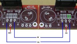
digi01 said:here is the connections,be careful physical balance in signal wiring from drv134 to 4780 should be maintained.
z
Thank you digi01, that is how I will do it then

maxw said:
This will not work, as you can't invert the input by swapping the input/ground connection for the inverted board. You will need to create a inversion circuit, or used a balanced driver chip like the DRV134.
digi01 said:here is the connections,be careful physical balance in signal wiring from drv134 to 4780 should be maintained.
Exactly! It should work fine, and be similar to the Jeff Roland Concentra design.
http://www.jeffrowland.com/images/review16d2.jpg
--
Brian
maxw said:Thank you digi01, that is how I will do it then
If you need and extra digi01 board for the DRV134, I can send you one.
--
Brian
Banned
Joined 2002
BrianGT said:
If you need and extra digi01 board for the DRV134, I can send you one.
--
Brian
You could send me 2 : O ) Please
BrianGT said:
If you need and extra digi01 board for the DRV134, I can send you one.
--
Brian
Yes, thanks. I have a few things I my "BGT" shopping list, will email you later
Originally posted by BrianGT
Dear Brian,
Do you mean you can send others the "schemtic and PCB" file ?
Please send me one ?
By the way, I am new to the "Chip Amp" world.
Will anyone give me the "link" for the schematic of "BPA 200" and Jeff Roland Model12 !!!!!
Thank You Very Much !
Thomas

thomasfw said:Will anyone give me the "link" for the schematic of "BPA 200"
See the first post
Interesting, as the 4780 contains two 3886, which is already capable of driving 4 ohm loads, and is parrallel in Brian's boards (2ohm stable??) the bridged vesrion can be assumed to be capable of driving though speakers at 4 ohm with reasonable power.
Is my understanding correct and what power will be available with sufficient supply?
Is my understanding correct and what power will be available with sufficient supply?
UPDATE!
Well almost a year later and I'm building this amp
I'm using a case and heatsinks from an old amp which I gutted:
And 2x LM4780 kits , 2x Line driver boards from Digi01, using a high cap and snubber psu and 2x 300VA 18V toroids.
The BPA-200 document says use 0.1% resistors so I got 1% ones and matched them by hand. I used Elna audio caps for the caps on the PCB, 330uF, and Elna starget audio for the Ci caps. Here is the completed amp modules:
And testing them out:
I'm still waiting for the caps and one line driver PCB to arrive so I can't put it together yet but I have a Q....
Will the DRV134 act as an input buffer?
Well almost a year later and I'm building this amp
I'm using a case and heatsinks from an old amp which I gutted:
An externally hosted image should be here but it was not working when we last tested it.
And 2x LM4780 kits , 2x Line driver boards from Digi01, using a high cap and snubber psu and 2x 300VA 18V toroids.
The BPA-200 document says use 0.1% resistors so I got 1% ones and matched them by hand. I used Elna audio caps for the caps on the PCB, 330uF, and Elna starget audio for the Ci caps. Here is the completed amp modules:
An externally hosted image should be here but it was not working when we last tested it.
And testing them out:
An externally hosted image should be here but it was not working when we last tested it.
I'm still waiting for the caps and one line driver PCB to arrive so I can't put it together yet but I have a Q....
Will the DRV134 act as an input buffer?
Hey Maxw, I'm was in your shoes...
I got almost all the parts about a year ago but haven't done anything with them yet. I have been & will be following your progress. I'll let you do the trouble shooting & then I'll get out my tools... Keep us updated!
BTW - Why only 18v, would the 25v be too much? What are you powering the Digi boards with?
I got almost all the parts about a year ago but haven't done anything with them yet. I have been & will be following your progress. I'll let you do the trouble shooting & then I'll get out my tools...
Keep us updated!BTW - Why only 18v, would the 25v be too much? What are you powering the Digi boards with?
cdoggy81 said:Hey Maxw, I'm was in your shoes...
I got almost all the parts about a year ago but haven't done anything with them yet. I have been & will be following your progress. I'll let you do the trouble shooting & then I'll get out my tools...
hehe, ok fair enough.
cdoggy81 said:BTW - Why only 18v, would the 25v be too much? What are you powering the Digi boards with?
because I can get 18V cheaply and 25V not. The 18V will be 25VDC once rectified etc. I will run the BLD boards off the same rails.
Well I've finished the amp.
I used 54,400uF of capacitance per channel. The DRV134s add 6dB of gain so I set the LM4780s to about 16x gain to compensate (they are set to 33 normally).
It goes very well!! probably the least amount of hassel I've had in an audio project No DC offset, no hum, no crackle or thump on turn on or turn off, silent as.
Still have to finish some casing though:
I used 54,400uF of capacitance per channel. The DRV134s add 6dB of gain so I set the LM4780s to about 16x gain to compensate (they are set to 33 normally).
It goes very well!! probably the least amount of hassel I've had in an audio project
No DC offset, no hum, no crackle or thump on turn on or turn off, silent as.Still have to finish some casing though:
An externally hosted image should be here but it was not working when we last tested it.
- Status
- This old topic is closed. If you want to reopen this topic, contact a moderator using the "Report Post" button.
- Home
- Amplifiers
- Chip Amps
- BPA-200 from BGT LM4780 kit?