Well, I have to admit that I redid my differential-buffered-inverting gainclone that I had struggled to make with point-to-point wiring and a differential recieiver on my own PCB. I used the BrainGT snubberized LM3886 design. I'll post the cookie cutter pics of the modified version later, but for now, how about the performance?
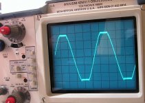
I have not listened yet, but have measured. Attached is a screen shot of an oscilloscope display of the snubberized GC, output of a sine wave at 1 KHz. 4x10,000 uF Elna for Audio in the P.S. and a 500 VA transformer shared between channels, both channels driven into 5 ohms. 10V/div with the appropriate probe.
Unless I'm reading this wrong, I found that I could get about 25 volts (50 peak to peak) into 5 ohms from about 20 Hz to 20,000 Hz. Plus and minus 20 V is 50/8 ohms, and 100/4 ohms, right? So this little GC is giving me about 125 watts into 5 ohms, and this is with both channels driven simultaneously. I could not get the GC to clip with my iPod on SE input. Doubling the voltage (balanced line driver to balanced input) allowed me sufficient signal to drive the amp into clipping into 5 ohms.
The power supply is about + and - 36VDC, this does NOT drop below 30VDC even when the amp is driven into clipping at 20Hz.
I double checked my measurements with a Tek DMM.
Anyway, looks like really good performance from the Brian GT gainclone, which is at the limits of the data specified by National Semiconductor. It looks like anything in excess of 20,000 uF per channel is unnecessary as the limits of the chip cause the clipping, not the limits of the power supply.
Has anyone else who has built this actually measured the power output and power supply drop? Are your results consistent?
Attachments
I think your math might be wrong. One, because the LM3886 will not drive that much output power into a 5 ohm load without major heat sinking and probably a fan. Two because when you figure power you take the peak voltage dividied by Sq. Rt. of 2 and this gives you RMS voltage. Then figure (V^2)/R = Power. I would run the level down to just before the start of clipping and measure the voltage. If this was 20V peak then output power = 40W for 5 ohm load. Try to measure your supply voltage under this condition as well for some good information. Am I reading your post wrong?
SL
Edit: I see now the rails don't drop below +/-30V. Running some numbers you are probably getting somewhere around 70 - 75W before the start of clipping. Check the datasheet and you will see that with a +/-30V supply and even a 4 ohm load the LM3886 never hits as much power as you originally calculated. Check the graph on page 14 and the output power with +/-30V for 4 ohms is around 85W and 6 ohms is 60W so 5 ohms is somewhere right in between.
power calcs
One reason I posted this is that I kind of forgot the math involved in making power calculations. So help here is appreciated. I did not mean to imply an RMS calc, that's why I posted the actual measurement.
My measurements indicate this GC provides plus and minus 22 to 25 volts before clipping, total swing of 44-50 volts peak to peak into 5 ohms.
What's the equation for computing power?
- Status
- This old topic is closed. If you want to reopen this topic, contact a moderator using the "Report Post" button.