Sorry, I know there are a million ground loop help posts on this forum, did my best to trouble-shoot and search but I have run out of ideas and need a little help…
I have constructed the stereo version of Brian’s LM3886 kit boards and am getting some ground loop hum. I am using one of the new snubberised power supply boards to power two amps. I have wired as directed. The problem I am having is that the amps are dead quiet when there is no input connected or when only one input is connected, but when two inputs are connected I get loud hum. The trouble shooting I have done:
Both input RCAs are insulated from the chassis.
Input cable from RCA to amp board is dual core shielded with the shield tied to ground at the RCA end only.
Chassis is grounded to earth wire of input 240VAC.
Hum is the same with CHGND connected to chassis or not.
I can induce the same hum by linking a single RCA cable between the two input RCA jacks (with or without chassis ground on pcb connected).
I suspect that the ground loop is happening when the two signal grounds on the amp boards are joined at the signal source and that the othe side of the loop must be through the power supply board. Am I on the right track? Can anyone offer any suggestions?
Thanks for your help guys,
Chris
steenoe said:That kind of hum behavior you have , points to a problem with the rectifierboard.
Steen.
No, I don't think so.
The problem is that there is probably a long distance between the two channel's power ground and the PSU gound.
What I mean by this is that the two boards with the chips must be close to each other so that the ground wires are as short as possible.
Brian has sent me some boards for me to try (thanks Brian) and I'm building an amp with them.
Should be finished, but I have been busy...
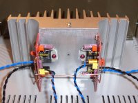
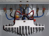
It's almost done, but I think you can get the picture.
The solid copper wire joins the power grounds of the two boards.
The center point of this solid copper wire connects to the PSU ground.
The ground arrangement on the PCB is not the ideal, because the power ground point should be only one, in a star arrangement. I am joining PG+ and PG- with a wire.
Attachments
Carlos,
i think im missing something here, but i dont see how your power ground arrangement is different from using the CHG pads? How is the CHG pad different from the center of your copper wire joing the PG+ and PG-?
The way i see it, they are connected to the same things...
Also, why is keeping ground wire short so important?
EDIT: and where will you connect power ground wires from rectifier now?
homer09 said:How is the CHG pad different from the center of your copper wire joing the PG+ and PG-?
First - this has nothing to do with CHG. This is all about the circuit ground.
The most important part is the heavy wire between the two channels. These boards each have a local star, which is fine, but then each board has two returns to the PSU board which is not ideal - especially if the PSU board supplies two channels.
I presume Carlos will connect PG+ and PG- from the PSU board to the center of the wire joining the two channels. This will form a central star at this point which branches to the local stars on each circuit board.
My P2P amp was dead silent - the two amps I've built with these boards have a very slight hum. It isn't at all noticeable unless you put your ear to the woofer, but it is there. If one is not careful about the wiring (match the lengths of all the ground wires and keep them short) I think it turns into a bigger problem.
Ah, now you have me thinking... I was going to attack this problem tonight, but after reading Carlos' suggested wiring, I had assumed that by "The center point of this solid copper wire connects to the PSU ground" he meant that I should tie the PG+ and PG- at the PSU to make one ground, and to use one wire to connect that to the centre of the power ground joining the two amp boards. Jeff talks of using the PG+ and PG- (two wires) and joining them to that same point. Does it make a difference?
Thanks again everyone for the input. Hope to have this sorted out tonight before I go away.
Cheers,
Chris
Thanks again everyone for the input. Hope to have this sorted out tonight before I go away.
Cheers,
Chris
jeff mai said:
...
My P2P amp was dead silent - the two amps I've built with these boards have a very slight hum. It isn't at all noticeable unless you put your ear to the woofer, but it is there. If one is not careful about the wiring (match the lengths of all the ground wires and keep them short) I think it turns into a bigger problem.
I have the exact same problem (very slight hum) whether there is anything connected to the amp or not. The wiring from the amps and the power board is pretty long so it sounds like if I reroute/shorten the lengths, I may be able to eliminate the hum?
I've noticed that some people twist their power/ground cables together. Is there some benefit to this or is it an asthetics issue?
regards
Dave
chrish said:Jeff talks of using the PG+ and PG- (two wires) and joining them to that same point. Does it make a difference?
No, it shouldn't as long as you hook to the center of the wire between the two channels. Either way this point ends up being the main star.
phoneisbusy said:The wiring from the amps and the power board is pretty long so it sounds like if I reroute/shorten the lengths, I may be able to eliminate the hum?
Maybe. But maybe not. Mine are pretty short and of similar lengths and I still have a faint hum. I don't worry about it too much as I'm used to SE tube amps that have a lot of hum by any comparison.
If I were going to undo a "done" amp, I'd attack the problem the way Carlos is doing his. I think the results are more certain to be better.
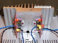
carlosfm said:I hope this is clearer now.
Two channels with single PSU.
PS: I don't use the on-board CHG connection to the chassis.
Almost clear, i understand your PSU power ground arrangement now. I imagine you will join the PG+ and PG- on the PSU boards with a rigid copper wire also and join its center to the PSU ground you labelled on your pic, right?
Now, im still unclear about chasis ground. You will be connecting your AC ground to the screw on the top of your heatsink right? What i dont understand, is what you will connect from your PSU to that and how.
obrigado para a clarificação Carlos
")
homer09 said:Almost clear, i understand your PSU power ground arrangement now. I imagine you will join the PG+ and PG- on the PSU boards with a rigid copper wire also and join its center to the PSU ground you labelled on your pic, right?
Right.
homer09 said:Now, im still unclear about chasis ground. You will be connecting your AC ground to the screw on the top of your heatsink right? What i dont understand, is what you will connect from your PSU to that and how.
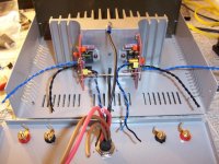
This amp will use my own external PSU (snubberized 3x4,700uf per rail, MBR16100 schottky diodes, heatsinked).

I have a big 4-pin Din plug, with two pins for ground (shunted).
The groung that comes from the PSU is only one, but I use two wires. Yes, double or very THICK wires for ground.
Still unfinished but just for you to get an idea.
Attachments
I get a similar hum if I have been an idiot and wire one of the input RCA's backwards. . . (signal and ground reversed).
I also discovered a bad IC this way (an old cheap one but it was part of my junk test-rig, and it had the leads reversed on one RCA - totally surprised me).
C
I also discovered a bad IC this way (an old cheap one but it was part of my junk test-rig, and it had the leads reversed on one RCA - totally surprised me).
C
homer09 said:Thanks, its clear now. i also see you dont kid around when it comes to the power supply
Nah...
homer09 said:Wire thickness... what happens if your wire isnt thick enough? should your ground wire be thicker than your V+ and V- wires? or is it also important for these to be thick too?
I use 2.5mm multi-strand copper wire for power gound, 1.5mm multi-strand copper for the voltage rails.
Of course, PSU wires should not be thin, and more critical is the ground.
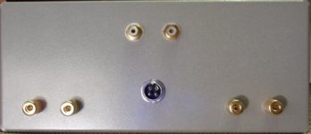
Done.
Kimber 4TC for signal and speaker wires (because I have some).
Everything soldered with silver solder (including all the components on the PCBs).
This massive heatsink doesn't get hot, even listening to Talking Heads' "Burning down the house" at half volume.
Kimber 4TC for signal and speaker wires (because I have some).
Everything soldered with silver solder (including all the components on the PCBs).
This massive heatsink doesn't get hot, even listening to Talking Heads' "Burning down the house" at half volume.
Attachments
- Status
- This old topic is closed. If you want to reopen this topic, contact a moderator using the "Report Post" button.
- Home
- Amplifiers
- Chip Amps
- Hum with Brian 3886 kits