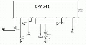
There have been recent posts about OPA541 and OPA549 which cover this topic. National makes an app note, I think 1142 or but it one of the posts, which will give you come connection guidelines if you want to parallel or bridge the OPA541.
There really isn't much to it. It's an op amp. Give it an input, power, close the loop, set some external components with simple Rs and Cs. Search for "OPA54*"
There really isn't much to it. It's an op amp. Give it an input, power, close the loop, set some external components with simple Rs and Cs. Search for "OPA54*"
I seem to be having a problem.. I'm getting straight DC on the output. I used this schematic. Is there something wrong with the schematic? I've tried it more than once on a breadboard with no luck.. Maybe something wrong with the chip, if the schematic is good?
Attachments
bigmike216 said:I seem to be having a problem.. I'm getting straight DC on the output. I used this schematic. Is there something wrong with the schematic? I've tried it more than once on a breadboard with no luck.. Maybe something wrong with the chip, if the schematic is good?
Try adding a resistor between pin 1 and ground - 'round 10 to 100 kohms depending on desired input resistance.
sidd_raj2002 said:hey is it ok if i use an unregulated supply.
my transformer is 20-0-20 5amp. is it good enought?
Yes. And Yes.
@bigmike - sounds like your input ain't connected to ground - for a start - just add a potentiometer at the input - properly wired - and if chip ain't damaged anyhow - I'm quite sure your problem will dissapear ...
Or if you intend to use a separated preamp - then just put some e.g. 50kOhm resistor between pin 1 and gnd ...
Or if you intend to use a separated preamp - then just put some e.g. 50kOhm resistor between pin 1 and gnd ...
Stabist said:@bigmike - sounds like your input ain't connected to ground - for a start - just add a potentiometer at the input - properly wired - and if chip ain't damaged anyhow - I'm quite sure your problem will dissapear ...
Or if you intend to use a separated preamp - then just put some e.g. 50kOhm resistor between pin 1 and gnd ...
That did it! Thanks!! As you can tell, I'm new to opamps
hey guys i need help again,
i have made the circuit its finished the problem is when i start it the woofer that i have connected to it just does a hummmmmmm. even if i give an input still it hums.
as u guys told i have added a 10uf cap instead of .068uf at input and and i added a 22kohm resistor between ground and pin 1. i dont understand this. do u have any suggestions?
i know it might sound crazy but u do connect the input,output and powersupply ground together right?
- Status
- This old topic is closed. If you want to reopen this topic, contact a moderator using the "Report Post" button.
- Home
- Amplifiers
- Chip Amps
- op541 gainclone
