does it work with or without the 10k resistor ? anybody ? pleaseAmA said:i buy the BrianGT LM4780 PCB and i don't understand how work the mute and how to make it . please help me. thanx
 anyone ??
Is there a schematic for this amp? I am new to these boards. If you read the datasheet for the LM4780 found on National's site (www.national.com) it explains that Mute is controlled by current. If no current is pulled from the Mute pin then the IC will be in MUTE mode. So you should have a resistor from the MUTE pins to the negative supply rail to put it in PLAY mode.
Mute
The schematic is here, although its not very complete, doesn't include the power supply stuff for example, lacks pin numbers for the 4780, etc... Looking at it quickly, for example, I don't see an R8 and R9 (listed onmy board), and it has a RZ1 and RZ2 that are not indicated on my board. Maybe the R numbers correspond to the ones on the board, maybe not. They apparently have not had time to fully document this board, so it will require a little study, but you see that there is a 10K resistor from mute to the negative power supply. Put this in and good luck. Maybe reading the materials on the 3886 boards and 3875 boards will help.
Note- you need a 10K resistor or something close, because if you don't connect the mute pins to a negative voltage, you won't draw current from the mute pins, and this results in a mute condition.
") Thanx very much for your help
Thanx very much for your help Re: Lm4780 mute resistor
Cr*p...I just ruined a board trying to put a resistor on these pads. I pulled the pad right off the board while I was trying position the resistor just a little bit better after soldering one side.
Now I'll have to get a whole new board try to remove all the components off the damaged board & try again. I might just forget the mute this time. Has anybody had problems without the mute?
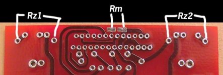
bike said:Brian sent me this picture because I had the same question. You need to put the mute resisitor at Rm. It is on the bottom of the PCB.
Cr*p...I just ruined a board trying to put a resistor on these pads. I pulled the pad right off the board while I was trying position the resistor just a little bit better after soldering one side.
Now I'll have to get a whole new board try to remove all the components off the damaged board & try again. I might just forget the mute this time. Has anybody had problems without the mute?
Member
Joined 2004
mute resistor
Kestrel
The easy way to solder he mute on 47g0 PCB is to melt a dab on the pads first.
Then bend lead at the resistor body by 90 deg then add one more
bend of 90 deg about 1/8 in down. it will look like a foot coming out of each end of resistor.
Tin both "feet" with solder.
just touch the tinned foot to one of the tinned pads and a quick touch of iron voila!
it sticks right away.
now with tweezers or screwdriver hold resistor against other pad and again a quick touch with iron an we have it soldered into place.
I suspect you wont have to do much repair if you can establish a spot of solder where each pad is.
Re: Re: Lm4780 mute resistor
yup. tried it... got a very silent amp.
there's just no sound no matter what. you need the muting resistors in order to have sound from the speakers.
kestrel200 said:
I might just forget the mute this time. Has anybody had problems without the mute?
yup. tried it... got a very silent amp.
there's just no sound no matter what. you need the muting resistors in order to have sound from the speakers.
pinkmouse said:Yes, you should be able to scrape of a bit of the solder resist on the remaining tracks and just use a normal 1/2w resistor.
Unfortunately I don't see any remaining tracks. Does anyone have a single board for sale???
Paging BrianGT
Brian,
Is there any chance I could talk you into selling me just the 4780 boards? I allready have two spare psu boards since I bought your CarlosFM snubber.
Thx
Mike
kestrel200 said:
Cr*p...I just ruined a board trying to put a resistor on these pads. I pulled the pad right off the board while I was trying position the resistor just a little bit better after soldering one side.
Now I'll have to get a whole new board try to remove all the components off the damaged board & try again. I might just forget the mute this time. Has anybody had problems without the mute?
Brian,
Is there any chance I could talk you into selling me just the 4780 boards? I allready have two spare psu boards since I bought your CarlosFM snubber.
Thx
Mike
- Status
- This old topic is closed. If you want to reopen this topic, contact a moderator using the "Report Post" button.
- Home
- Amplifiers
- Chip Amps
- Mute on BrianGT LM4780 PCB ?