Hwy, looks nice. Is the volume knob a sort of "remote control?" ")
Hey, you're Beta testing for everyone, not just us. And not just that the board works, or if the parts fit, but how easy the amp is to work with and how well it can integrate, etc. Try anything.
I always think if having my heatsinks exposed, but I've seen a few people now with internal sinks with this amp, and it appears to be fine. That's good to know. See, beta test succcessful.
First let me apologize to Russ and Brian. Half way through this project I realized that the meaning of beta is to test operation and not complete a product. I'm sorry, and next time I will just assemble and test in a "rough" enclosure.
Hey, you're Beta testing for everyone, not just us. And not just that the board works, or if the parts fit, but how easy the amp is to work with and how well it can integrate, etc. Try anything.
I always think if having my heatsinks exposed, but I've seen a few people now with internal sinks with this amp, and it appears to be fine. That's good to know. See, beta test succcessful.
HI Troy,
What you did there was worth the wait. Very nice amp.
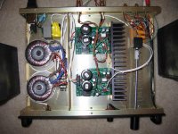
Ok, I am sure its just my eyes, but I only see one wire going to each input (probably actually a shielded pair but I can't tell). Where does the Input GND attach?
Nice work Troy, that's for sure.
Cheers!
Russ
What you did there was worth the wait.
Very nice amp. Ok, I am sure its just my eyes, but I only see one wire going to each input (probably actually a shielded pair but I can't tell). Where does the Input GND attach?
Nice work Troy, that's for sure.
Cheers!
Russ
BrianDonegan said:Hwy, looks nice. Is the volume knob a sort of "remote control?"
Hey, you're Beta testing for everyone, not just us. And not just that the board works, or if the parts fit, but how easy the amp is to work with and how well it can integrate, etc. Try anything.
I always think if having my heatsinks exposed, but I've seen a few people now with internal sinks with this amp, and it appears to be fine. That's good to know. See, beta test succcessful.
Yes I used a NON-magnetic coupler to extend the shaft so the pot could be board mounted on the input switcher brd(that isn't working
)That was to keep the signal path as short as possible.
ALL wiring is silver plated Copper with Teflon insulation.
The heat sinks are raised 1/2" from the bottom of the chassis and there are vents on the fin side of the bottom and 2 rows of the same vents on the top. Cooling should not be an issue. Especially since this is not a "party" amp.
The kit was easy to build, but man was the mounting of the LM3886 to the heat sink hard. I wish I had saved the pwr supply cap for last so I could get my screwdriver in. Instead I had to use a Phillips bit and a socket/ratchet to tighten the screw down. Note to self, always leave room for tools where fasteners go....
With the volume control @ min there is absolutely NO noise. Until I get my LEDs mounted for the input identification and the volume indicator there is no way to tell it's on other than the position of the pwr switch.
Russ White said:HI Troy,
What you did there was worth the wait.
Ok, I am sure its just my eyes, but I only see one wire going to each input (probably actually a shielded pair but I can't tell). Where does the Input GND attach?
Nice work Troy, that's for sure.
Cheers!
Russ
If your referring to the input of the amp, it is Silver plated copper, teflon insulated co-ax wire from Steve @ Apex.jr.
I have both co-ax and sheilded twisted pair from him. Great stuff at a great price.
Edit: The white wire in the back of the chassis is the sheilded twisted pair. The black wire on the right side is STRANDED cat 5 for DC control to the relays from the front mounted Greyhill switch.
Hwy, looks nice. Is the volume knob a sort of "remote control?"
I meant the knob itself. looks like it's long enough to reach the couch!
You don't know how happy that makes me feel.rabstg said:
With the volume control @ min there is absolutely NO noise. Until I get my LEDs mounted for the input identification and the volume indicator there is no way to tell it's on other than the position of the pwr switch.
Of course Brian and I (and some others) have noticed that for a while, but it validates that all of the advice from Maruo and others that went into the layout paid off.As far as you relay problem, I would suspect(but you probably already checked this) you had your pins (NO NC) swapped maybe?
Cheers!
Russ
BrianDonegan said:
I meant the knob itself. looks like it's long enough to reach the couch!
Believe it or not, that is the "small one" of the two.
It is the second pair from the left in the following link:
http://www.apexjr.com/knobs.htm
The small blk ones are plastic and that is what is currently being used as source selector.
I LOVE the ones on the right. For the volume knob I have drilled a hole in the detent for the 3mm LED and am having both the volume and switcher knob anodized black.
There will be three 3mm LEDs on top of the input selctor switch to indicate which input is active.
Did I mention I need details of you two's volume control (Kookaburra) and input selector? Need to see if they will fit and what is required to swap out my hack job BEFORE I make any more holes.
Kookaburra will fit for sure, and if you use it with this amp you can omit both the input and output buffers.
Size is 4.1" x 2.1".
My input selector (just finished tonight still testing, so far so good) is roughly the same size, but it has not been optimized at all yet. I will get with Brian to find out what the production version will be.
Size is 4.1" x 2.1".
My input selector (just finished tonight still testing, so far so good) is roughly the same size, but it has not been optimized at all yet. I will get with Brian to find out what the production version will be.
Russ White said:
As far as you relay problem, I would suspect(but you probably already checked this) you had your pins (NO NC) swapped maybe?
Cheers!
Russ
I have not started trouble shooting yet ,but my suspicion is that the transformer (yellow tape since it was not mounted and the rectifiers and cap were exposed) may be too high a voltage, Or I did not do a good enough solder bridge somewhere on the bottom of the PCB.
I should have just tried my hand at etching and fabbed a PCB. Instead I put jumpers and solder bridges on the bottom.
I need to see what the voltage is after the regulator (7812) and see if it is a power issue or control(input selector) issue.
I doub it is a signal pinout issue since the relays don't engage when the input selector is turned. I "ASSUME" it is a pwer issue.
Loud hum with open inputs
Well, I´m not sure if I should call it a problem, but for better understanding: With open inputs my REV C ( to be seen here: http://www.diyaudio.com/forums/showthread.php?postid=744874#post744874 ) hums like hell. With shorted input there is no noise, except of a very faint trafo hum. So it is no real problem as with an input device connected there is no noise at all.
But what is the reason ? Never had such a behavior before ...
Re: Loud hum with open inputs
High i/p impedance, quite high gain and few unshielded parts is my guess
mike
SmellOfPoo said:With shorted input there is no noise, except of a very faint trafo hum. So it is no real problem as with an input device connected there is no noise at all.
But what is the reason ? Never had such a behavior before ...
High i/p impedance, quite high gain and few unshielded parts is my guess
mike
Re: Re: Loud hum with open inputs
Hi Russ,
I´ll try that as soon as I´m home. Thanks!
Gerd
Russ White said:. As a test try leaving mains GND unconnected and see if the hum goes away.
Hi Russ,
I´ll try that as soon as I´m home. Thanks!
Gerd
Well I bumped the wires a bit hard last night, and activated the smoke emitter, the poor resistor connected to the earth line is absolute toast. Replaced it but getting a little hum now.
Could the capacitors have packed up in the process? Or do you think the chip is damaged? Still plays fine... just the hum.
Could the capacitors have packed up in the process? Or do you think the chip is damaged? Still plays fine... just the hum.
Grnd loops
A few simple rules I follow.
1. Isolate the signal grd from pwr or chassis grnd. All 3 are different.
2. tie the left and right grnds together @ the input. They should be tied together @ the source output too.
3. Cross your fingers, stand on your left foot and chant a prayer to the guru gods of ground that you didn't miss anything during construction that may cause a ground loop.
the poor resistor connected to the earth line is absolute toast
Which one? And what exactly shorted out?
heck I should have opened a new thread, don't want to hijack... got caught up in the moment
Its the standard IGC from decibel dungeon, the resistor sits in parallel with a 100nf cap between the PGS and the earth... It basicaly connects the PGS to the chassis, which in turn is connected to the mains' earth.
I was doing some testing work with everything open so I don't know what exactly shorted, the moment I saw smoke I ripped the powercable out (benefit of banana plugs)...
No scorching on the veroboard (don't laugh), only the resistor is totaly burned out (brown), and it looks like some brown marks on the outside of the one 1000ufd cap (which is adjacent on the board), I think this is just a smoke stain though.
Was quite surprised that it still works, as the first one I build completely blew up after a small shortcircuit, with some brown stuff actualy comming out of a crack in the chip...
- Home
- Amplifiers
- Chip Amps
- My "audiophile" LM3886 approach