Hi Paolo,
I answer to your post:
current test: I have compact of the tests with the bridge that has signaled you. I have not gotten "acoustic" results of relief with similar impedances to the load. To have "electromechanical" benefits you have to increase the Zout to at least 10 Zload. In any case, the result is not usable for commercial multi- drv spk, because you have un "exaltations" of much DB in the zones of resonance, then to low frequency ( woofer ) and to the intersection (crossover) of the drivers. The result is a dominated sound by that frequencies and then non acceptable.
An interesting system to have the advantages of the " current driven " limiting this problem is the "firstwatt" structure, that would be able be done with this bridge... If you wants try before me...
Clipping: I understand thing want say, but you considers that LM318 goes in clipping only in the cases of elevated output current ( one of the advantages to use this topology is that the limitation of the current will make limiting the LM318 out voltage ).
I the rest understands it, but I have prefered limit the complexity of the circuit for various reasons. In any case you considers that with 22pF among 3 and 6 (LM318) get a complete feed-forward of the chip. With the same value among 2 and 6 a back-forward. If you lead two 9V zener (catode common) among the 2 and the 6, get a good limit of current, but introduce an enough ability, for example, to neutralize entirely the feed-forward (22pF) in the rev3.
If you uses a active net , the only way to hold it " out of NFB " is use an elevated time costant, but I have not measured never condition critical things by justify this select ( never chip shock ). I have foreseed a net of protection of the spk for the "limit cases".
In connection with Zin, if uses a buffer ( not inverting ) to driven a current pump it is able have the Zin that prefer. From it case of MyREF, the particular configuration "high impedance inverting " of LM318 is not a lot of flexible for this use...
Ciao
Mauro
derekyu said:Hi, White,
I just received the pcb... it is .............. pretty ... good
Glad to hear it.
") Enjoy!
Enjoy!White, its me again.
I wonder whether I can use same type NPN for Q1,2,3.
The speaker protector scheme is quite special. (Maybe I have not read the scheme long). The relayer is on the (-) but not the (+). Is it possible for me to adopt it as headphone amp protector? And need I change some parts as the output of the headphone is quite low?
I am sorry to ask you so much question.
Bty, thanks
derekyu said:White, its me again.
I wonder whether I can use same type NPN for Q1,2,3.
The speaker protector scheme is quite special. (Maybe I have not read the scheme long). The relayer is on the (-) but not the (+). Is it possible for me to adopt it as headphone amp protector? And need I change some parts as the output of the headphone is quite low?
I am sorry to ask you so much question.
Bty, thanks
I am sorry I cannot answer your question as I am not experienced enough yet. I am actually not very familiar with the details of the protection circuit as I did not design it, Mauro did. Maybe Mauro can answer your question.
Ciao Mauro,
if with "Paulo" you was referring to me... that's not what I was asking.
Let me try to explain better what and why... (sorry for the OT! ).
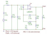
As I have said in some other thread, I have already built a "toy" test chip amplifier, which is sort of NIGC (using LM3875) with (adjustable) current feedback net added. By means of a trimpot I can set its output impedance (see attached schematic).
This test amplifier have shown some quite interesting results when listening to it with different output impedance settings (I have already tried it with several different -and absolutely "normal"- multi-way loudspeakers, in different systems, rooms, etc).
Compared to a normal GC (or to itself with Zout set to the minimum), the most evident effect of a moderately high (8 ~ 16 ohm) Zout is a much improved sense of "dynamic", "velocity", "pace" and "rhythm"; in a word, the music seems to get more "life", if you can understand what I mean.
(other less pronounced effects are a feeling of better "smoothness" and a sense of "bigger" sound, including better imaging).
As far as I have tried up to now, each system (loudspeaker,cables,room,...) seems to show a (rather wide) "sweet spot", i.e. some Zout value which gives the best "musical" results (to date I have always found it to be in the range of about 4 to maybe 16 ohm or such, at least on speakers with a nominal impedance of 8 ohm).
Reducing Zout to increase the DF makes the sound "dull", "dead" (and usually also a bit "harsh" - same results as with a "true" GC), while further increasing the Zout does not bring further improvements to the sound quality. On the contrary (and quite obviously!), setting it too high usually results in screwing up the bass response (going to the maximum also make the sound a bit harsh again... but I guess that's because with my test amplifier this setting also imply a reduced amount of total NFB).
According to countless articles from various authors, you get the best sound quality when you achieve a nearly critical damping of the loudspeaker... of course, with today typical loudspeakers, varying the amplifier Zout you can easily achieve this result.
My easy guess is that, quite likely, the aforementioned perceived qualities (except probably for the harshness/smoothness) of the reproduced sound, or lack thereof, can be closely related to the total damping.
BTW, even with the "best" possible setting, my toy amplifier is still far from approaching the quality of my current reference (which is my tube amplifier). Compared to the reference, the music message appears to be somewhat "simplified", poorer; the image is worse, and overall the sound appares somehow "mechanical", less "natural".
OK, now let' go back to the point...
Judging from both a "theoretical" point of view as well as from the comments I've heard from people who have tried your design, I guess (and hope!!) that your "my_ref" should be way MUCH better than a trivial GC... (again, I'm really very curious to try it myself and compare to my tube amplifier!) and it definitely should do a much better job than my current "toy" test amplifier.
Yet I would be very curious to see how this varying DF "trick" behave using a much better design to start with, to understand whether it is really a general effect or it is only a trick limited to some (flawed?) design...
got the point? suggestions?
mauropenasa said:Any considerations:
By Paulo:
If you want use the current pump autonomously ( for the current tests ) are able use the only bridge, with a input buffer ( to maintain balance the resistances of the bridge ) .
if with "Paulo" you was referring to me...
that's not what I was asking. Let me try to explain better what and why... (sorry for the OT!
).As I have said in some other thread, I have already built a "toy" test chip amplifier, which is sort of NIGC (using LM3875) with (adjustable) current feedback net added. By means of a trimpot I can set its output impedance (see attached schematic).
This test amplifier have shown some quite interesting results when listening to it with different output impedance settings (I have already tried it with several different -and absolutely "normal"- multi-way loudspeakers, in different systems, rooms, etc).
Compared to a normal GC (or to itself with Zout set to the minimum), the most evident effect of a moderately high (8 ~ 16 ohm) Zout is a much improved sense of "dynamic", "velocity", "pace" and "rhythm"; in a word, the music seems to get more "life", if you can understand what I mean.
(other less pronounced effects are a feeling of better "smoothness" and a sense of "bigger" sound, including better imaging).
As far as I have tried up to now, each system (loudspeaker,cables,room,...) seems to show a (rather wide) "sweet spot", i.e. some Zout value which gives the best "musical" results (to date I have always found it to be in the range of about 4 to maybe 16 ohm or such, at least on speakers with a nominal impedance of 8 ohm).
Reducing Zout to increase the DF makes the sound "dull", "dead"
(and usually also a bit "harsh" - same results as with a "true" GC), while further increasing the Zout does not bring further improvements to the sound quality. On the contrary (and quite obviously!), setting it too high usually results in screwing up the bass response (going to the maximum also make the sound a bit harsh again... but I guess that's because with my test amplifier this setting also imply a reduced amount of total NFB).According to countless articles from various authors, you get the best sound quality when you achieve a nearly critical damping of the loudspeaker... of course, with today typical loudspeakers, varying the amplifier Zout you can easily achieve this result.
My easy guess is that, quite likely, the aforementioned perceived qualities (except probably for the harshness/smoothness) of the reproduced sound, or lack thereof, can be closely related to the total damping.
BTW, even with the "best" possible setting, my toy amplifier is still far from approaching the quality of my current reference (which is my tube amplifier). Compared to the reference, the music message appears to be somewhat "simplified", poorer; the image is worse, and overall the sound appares somehow "mechanical", less "natural".
OK, now let' go back to the point...
Judging from both a "theoretical" point of view as well as from the comments I've heard from people who have tried your design, I guess (and hope!!) that your "my_ref" should be way MUCH better than a trivial GC... (again, I'm really very curious to try it myself and compare to my tube amplifier!) and it definitely should do a much better job than my current "toy" test amplifier.
Yet I would be very curious to see how this varying DF "trick" behave using a much better design to start with, to understand whether it is really a general effect or it is only a trick limited to some (flawed?) design...
got the point? suggestions?
Attachments
Paolo,
Here's some links regarding output impedance you may find interesting.
http://sound.westhost.com/project36.htm#reference (There's a part in the "conclusion" talking about hi-impedance transistor amps sounding like tube amps)
http://sound.westhost.com/impedanc.htm#_damping
Greg
Here's some links regarding output impedance you may find interesting.
http://sound.westhost.com/project36.htm#reference (There's a part in the "conclusion" talking about hi-impedance transistor amps sounding like tube amps)
http://sound.westhost.com/impedanc.htm#_damping
Greg
Ciao Mauro,
sorry, I have not quite understood what you mean here.
(we should definitely move this discussion to the italian forum...)
let me see if I have understood... you claim that, regardless of the load impedance, the 3886 internal current limiting protection triggers (@ ~11A ) before the LM318 output voltage reach ~9V ?
and what about the 3886 reaching its maximum output voltage swing (e.g. spkr presenting a high-Z load at some LF resonance...)?
what do you mean with "chip never shock"? that the two chips do have "instantaneous" recovery from any clipping/overload/protection condition?
well, this open up a whole lot of new questions...
why have you chosen that configuration instead of a non-inverting one?
which is the input impedance of "MyREF" as it is? at a first glance, I would say approximately R12 + (R10//R7) i.e. some ~3.5 Kohm. Or am I overlooking something?
Wouldn't it be possible to increase Zin by increasing R12 & R7 and adjusting C12, C32/R42, etc. accordingly? What would be the drawbacks? Why have you chosen such a low Zin?!?
mauropenasa said:An interesting system to have the advantages of the " current driven " limiting this problem is the "firstwatt" structure, that would be able be done with this bridge... If you wants try before me...
sorry, I have not quite understood what you mean here.
(we should definitely move this discussion to the italian forum...
)Clipping: I understand thing want say, but you considers that LM318 goes in clipping only in the cases of elevated output current
let me see if I have understood... you claim that, regardless of the load impedance, the 3886 internal current limiting protection triggers (@ ~11A ) before the LM318 output voltage reach ~9V ?
and what about the 3886 reaching its maximum output voltage swing (e.g. spkr presenting a high-Z load at some LF resonance...)?
but I have not measured never condition critical things by justify this select ( never chip shock ).
what do you mean with "chip never shock"? that the two chips do have "instantaneous" recovery from any clipping/overload/protection condition?
In connection with Zin, if uses a buffer ( not inverting ) to driven a current pump it is able have the Zin that prefer. From it case of MyREF, the particular configuration "high impedance inverting " of LM318 is not a lot of flexible for this use...
well, this open up a whole lot of new questions...
why have you chosen that configuration instead of a non-inverting one?
which is the input impedance of "MyREF" as it is? at a first glance, I would say approximately R12 + (R10//R7) i.e. some ~3.5 Kohm. Or am I overlooking something?
Wouldn't it be possible to increase Zin by increasing R12 & R7 and adjusting C12, C32/R42, etc. accordingly? What would be the drawbacks? Why have you chosen such a low Zin?!?
UnixMan said:Ciao Mauro,
which is the input impedance of "MyREF" as it is? at a first glance, I would say approximately R12 + (R10//R7) i.e. some ~3.5 Kohm. Or am I overlooking something?
Wouldn't it be possible to increase Zin by increasing R12 & R7 and adjusting C12, C32/R42, etc. accordingly? What would be the drawbacks? Why have you chosen such a low Zin?!?
Guess I do not understand the operation of the LM318. I thought R12 and R13 set the input impedance of this circuit. If it is 3500 ohms as per your calculations most capacitor coupled preamps are out.
Does R13 not effect anything?
George
Just to add some noise to the thread, rigged the amp up today!
Hasn't exploded so far, R4 and R27 get pretty hot. As long as they don't desolder themselves I'm fine with it
Basically no humming using low quality cabling, cheap connectors and no shielding (the trafo is on top of the amp (mounted it on the heatsink facing downwards))
So that's rather awesome
But so far there's too little bass on my 6Ohm speakers.
Letting it run over night. Maybe it's just the cheap cabling or them cheap speakers. And the PC source maybe.
Anyway, thanks Mauro for the excellent design!
And Russ and Brian for their efforts =)
Too bad i don't have a camera here

Member
Joined 2003
I have not had a chance to look at the circuit myself, but 3500 Ohm Zin is way too low. I was reading back a few pages and found this post where Mauro states that Zin is 100K.UnixMan:Wouldn't it be possible to increase Zin by increasing R12 & R7 and adjusting C12, C32/R42, etc. accordingly? What would be the drawbacks? Why have you chosen such a low Zin?!?
analog_sa said:Of course it's a 100k. The 3k32 resistor is not going into virtual ground.
mmmh... 318 inverting... 3886 inverting again...
Oops! I should have looked more closely at the schematic before speaking...
If now I have understood it correctly, globally the whole thing is behaving much like a non-inverting op-amp with gain set by the divider formed by R7 and R10... then you're right. The input impedance basically is set by R13.
OK!

REV C monobloc PCB correction
I must apologize. The diagrams I had of the relay which I used to make the part in eagle were not marked as to which way they were drawn, from the top, or from the bottom. So I made the part as if it where drawn from the top. Well that bit me in the buns. It turns out now that I finally found a real datasheet that the diagram was actually drawn from the bottom, so I had the pins swapped.
I had to order the relay, I did not have any on hand so I could not check.
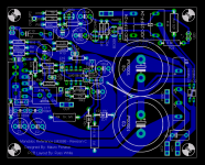
Now that I know it was wrong I have fixed it. Here is the corrected PCB.
If any of you etched the faulty version, it is simple to rig a fix, simply cut the OUT GND trace at the relay pin and run a jumper wire from the opposit pin to the faston pad for OUT GND.
Here is the fixed PCB. PDFs for copper and component to follow.
I must apologize. The diagrams I had of the relay which I used to make the part in eagle were not marked as to which way they were drawn, from the top, or from the bottom. So I made the part as if it where drawn from the top. Well that bit me in the buns. It turns out now that I finally found a real datasheet that the diagram was actually drawn from the bottom, so I had the pins swapped.
I had to order the relay, I did not have any on hand so I could not check.
Now that I know it was wrong I have fixed it. Here is the corrected PCB.
If any of you etched the faulty version, it is simple to rig a fix, simply cut the OUT GND trace at the relay pin and run a jumper wire from the opposit pin to the faston pad for OUT GND.
Here is the fixed PCB. PDFs for copper and component to follow.
Attachments
Thanks for the update Russ
There is no learning without mistakes.
I wish I could forget all the times I've mirrored PCB patterns, etched the board and even stuffed them only to get burned when something just doesn't fit right. Frustrating!
Thankyou again for the update.
Mark
There is no learning without mistakes.
I wish I could forget all the times I've mirrored PCB patterns, etched the board and even stuffed them only to get burned when something just doesn't fit right. Frustrating!
Thankyou again for the update.
Mark
Hi all,
Other suggestions:
- The values of voltage and power of my BOM is always to consider as least values of departure. In any positions ( i.e. C4, C19 ) I have used a footprint more great to allow to use even cap with VL> 100V. They remember that in the cap a greater work voltage ( and a greater encumbrance ) is much often a guarantee of better quality.
- The cap that are connected to the output signal have to have a VL = or >100Vdc.
- R1, R4, R24, R27, R14 dissipate less of 1W but they heat much, for which be necessary use 2-3W, but does it main point is that are of great dimensions (+ dissipation) and they climb on as it says Brian ( lift from the card ).
- ZD1-ZD4 have it same problem: they have to be up by the card to heat of less.
R3 and R26 even. They remember that if fairies of the tests to full power, R3 and R26 are able arrive to temperatures superior to 100°C.
- The cap C9 , C24, C13, C29 have to be " audio grade ", but I seems that the select the Brian is good.
- The Output Relay is on the power GND for any reasons, but the principals are a layout more simple and a voltage swing (on the switches of the relay) the more reduced (-diaphony ) . from the point of view of the operation, not change much, given that the spks come "off" in any case ( no current, no sound ).
- LM318 is connected in "floating" because has not a direct reference to the GND. For this reason it reverses the input signal but the Zin is 100K. If inserts a Res among 2 and 6 pins, the operation changes and pin 2 becomes " virtual gnd ", and Zin = 3.3K// ( Res 2-6 ). Here an example of the difficulties of insertion of compensation nets; The floating connection is a lot of tender to the polarization nets...
Other precise statements: My_REF is a very "musical" circuit and for this has wanted share it with the forum. His performances have convinced me to not increase the complexity of the circuit, because not there are particular problems of operation. This circuit is not a " commercial-professional amp ", and I have not dimensioned the components to do from it an use "industrial". This circuit is not applicable to is second-hand as "Harmonizer" or in "continuos full power " as the amp from disco...
Ciao
Mauro
- Home
- Amplifiers
- Chip Amps
- My "audiophile" LM3886 approach