Re: Using Revision A boards for Rev C
Yes, I understand you can go that route, and really it should work fine.") But I really have a couple of reasons for my PCB layout.
But I really have a couple of reasons for my PCB layout.
1) I want 5 channels in one enclosure for 5.1 listening.
2) I want a seperate PS from the amp board so that I can easily swap amp sections if that is all that has changed.
3) I don't really like "hillbilly rigging" if I don't have to.
Yes those PE trafos woprk great! I have been listening to my standard NIGC with one for the better part of a week! What a steal! Those are perfect gainclone trafos.
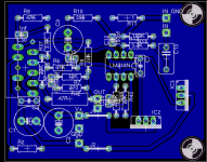
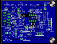
Here is my latest iteration with the additon of LM7812 and LM7912 voltage regulators on board for the opamps.
Not finished quite yet as I still do not have some bypass caps in place for the VRs. Also I will add more pads for larger input caps.
Cheers!
Russ
Panelhead said:
Russ,
Looking it over it looks like there are 4 resisitors and four capacitors added per channel. I hate to do it, but it should be fairly easy to "hillbilly rig" these 16 components to the circuit board. George
Yes, I understand you can go that route, and really it should work fine.
But I really have a couple of reasons for my PCB layout.1) I want 5 channels in one enclosure for 5.1 listening.
2) I want a seperate PS from the amp board so that I can easily swap amp sections if that is all that has changed.
3) I don't really like "hillbilly rigging" if I don't have to.
Yes those PE trafos woprk great! I have been listening to my standard NIGC with one for the better part of a week! What a steal! Those are perfect gainclone trafos.
Here is my latest iteration with the additon of LM7812 and LM7912 voltage regulators on board for the opamps.
Not finished quite yet as I still do not have some bypass caps in place for the VRs. Also I will add more pads for larger input caps.
Cheers!
Russ
Attachments
Re: New Boards
If Mauro blesses the design I would be glad to offer some boards for sale as soon as I can test the board, which would likely be in the next month or so as you say.
In the meantime, there is certainly nothing wrong with the REV "A" circuit. It sounds simply stunning.
Cheers!
Russ
Panelhead said:Russ,
I will wait on building then myself. I do not like having 16 components hanging off the board either. This will triple the chance of bad or shorted connections.
Do you think you will have Rev 3 boards available for sale by sometime next month?
George
If Mauro blesses the design I would be glad to offer some boards for sale as soon as I can test the board, which would likely be in the next month or so as you say.
In the meantime, there is certainly nothing wrong with the REV "A" circuit. It sounds simply stunning.
Cheers!
Russ
Alas, it appears there are a few problems with my layout.
1) Lm7812/7912 may not be suitable as the input voltage would be close to its maximum. So I will redesign using the RCZ net as Mauro did.
2) I need to include some sort of soft start/delay circuit to elminate the turn on thump.
3) Grounding may be somewhat iffy. Still looking at that.
1) Lm7812/7912 may not be suitable as the input voltage would be close to its maximum. So I will redesign using the RCZ net as Mauro did.
2) I need to include some sort of soft start/delay circuit to elminate the turn on thump.
3) Grounding may be somewhat iffy. Still looking at that.
Russ White said:
1) Lm7812/7912 may not be suitable as the input voltage would be close to its maximum. So I will redesign using the RCZ net as Mauro did.
2) I need to include some sort of soft start/delay circuit to elminate the turn on thump.
Would a larger value cap on the mute release pin suffice?
edit: After re-examining the PCB, would any cap on the mute release suffice?
Edit 2: After looking at the LM318 data sheets, the supply voltages are good @ +/- 12VDC. The input voltage is refering to signal input not pwr supply input.
rabstg said:
Would a larger value cap on the mute release pin suffice?
edit: After re-examining the PCB, would any cap on the mute release suffice?
Edit 2: After looking at the LM318 data sheets, the supply voltages are good @ +/- 12VDC. The input voltage is refering to signal input not pwr supply input.
I am not sure if the mute cap would work or not.... It just might.
I was referring to the max input voltage on the LM7812/7912 which is 35V. Which happens to be just about what the rails would be at.

Hi all,
How to have said various turned in the thread, this circuit is a lot of nonelementary ( even if with little components ).
The matter of the "thump" is not easily that can be managed because there are 2 Opamp nesting with common NFB, and LM3886 is in configuration to bridge. The mute of LM3886 is unusable, because LM318 would go to clipping for follow the LM3886 STBY.
I have recommended to Russ to follow more possible my layout of the circuit to avoid problems of: oscillations and Ground loop.
The matter of the external Hi-cap doesn't exalt me because sets the "endless" problems described in the Thread " snubber yes or not " but it is a personal choice.
Naturally all am clear of interprets to like them my circuit, but in my layout it is "hidden" different years of technical "analysis"...
ciao
Mauro
D-A Question
I see the 14 volt relay for the output. Is there an issue using it to handle the turn on thump?
I do not like the thumps, several amps built have switches on the outputs to allow stabilization then turning on. I use double throw with 15 ohm rsistors on one side for loading and speaker connection on other. A realy is much better, no hassle.
George
Yes, Mauro's layout with the relay handles this quite nicely. I will add the same circuit to my layout as well, only for a single channel. I was really planning to all along. I was just not sure if I would do it on the same board or as a seperate board (maybe on the PS). I think now what I will do is a single channel complete with PS on a single board. I will try to emulate Mauro's star ground on the board, I see how he brings seperate ground traces together right between the large caps on his PCB design. I will do the same.
Hopefully I will have something to look at soon.
Really I am just doing this for my own pleasure, so if it is not useful to anyone no harm done.
Cheers!
Hopefully I will have something to look at soon.
Really I am just doing this for my own pleasure, so if it is not useful to anyone no harm done.
Cheers!
Hi George,
I still have a lot of work to do on the layout. My intention is to use all of the same techniques Mauro did to the best of my limited ability.
The only major defference will be that my board will be for a single channel monobloc. The reason is because I want to facilitate multi channel amps (such as 5.1).
Cheers!
Russ
Russ White said:...Really I am just doing this for my own pleasure, so if it is not useful to anyone no harm done.
Cheers!
Russ, your doing a great job, and attraching flies, myself included.
I will make suggestions so you, and Mauro, please feel free to continue slapping my hand as needed.
Mauro- Beautiful concept. I can't wait to hear it.
What do you think about using CarlosFM's Snubber 1.1 power supply in place of mauro's power supply? I am sold on the advantages of regulated over unregulated, but not sure if it will change the dynamics.
taken from http://www.diyaudio.com/forums/showthread.php?s=&threadid=56106&perpage=10&pagenumber=15
An externally hosted image should be here but it was not working when we last tested it.
taken from http://www.diyaudio.com/forums/showthread.php?s=&threadid=56106&perpage=10&pagenumber=15
- Home
- Amplifiers
- Chip Amps
- My "audiophile" LM3886 approach