Maybe someone already said what I'm going to say, but here goes anyway. I like that it has a passive Rf filter at the input. Digital sources usually put out some Rf energy that down stream circuits may not handle well. Since the output stage has no voltage gain, it seems like the input opamp would need much higher rails (power supplies).
I built a 3886 power amp using a circuit very similar to the Linkwitz Pluto circuit, with the output choke being the major diff., and it works great. Not sure why you'd want to complicate things. I'd be very concerned about phase margin unless I injected square waves in strategic places, and looked at how other nodes are handling it.
I built a 3886 power amp using a circuit very similar to the Linkwitz Pluto circuit, with the output choke being the major diff., and it works great. Not sure why you'd want to complicate things. I'd be very concerned about phase margin unless I injected square waves in strategic places, and looked at how other nodes are handling it.
Where is the science to support this preposterous conclusion?In the FE the path is the shortest possible with TH parts:
An SMD part would not make a great difference on traces lenght...................
I can see that an smd capacitor directly between the two opamp power pins can have a trace length of far shorter than the circuitous route shown in your accompanying extract.
Give me a ruler and a PCB and I will measure the difference. Possibly of the order of 40% to 50% of the route you have adopted.
The science clearly says you are wrong !!!!!!!!!!!!!!!!!!!!
Last edited:
I too am very suspicious of "why" cap tuning is having an effect on the "sound" quality.
The differences being heard by some members tells me the signal is being changed in their implementations.
That in turn leads to my conclusion that some of the implementations are corrupting the signal.
I cannot tell/conclude that none or only some some of the implementations contain no corruption of the signal.
It is possible that the lack of proper and adequate decoupling is leading to all these implementations emitting a corrupted signal.
If that were the case then would it be unreasonable to suggest that all the tunable implementations are actually sub-optimal?
That is not a conclusion.
I am asking you to be open minded enough to question "why" the tunable circuits behave as were are being told they do.
Sure, there is lots involved with tuning with components. Some can be explained and some cannot. To add to the complication, it seems that steady state signal testing alone may not be sufficient to pinpoint which change is technically better. Even if tested to be technically better, if it does not sound better, does one really know technically why? Complications complications.
Dario,
I see your Eagle PCB layouts have nice smooth transformation from thin traces to large pads. Did you use brute force or does Eagle PCB have the feature?
Dario,
I see your Eagle PCB layouts have nice smooth transformation from thin traces to large pads. Did you use brute force or does Eagle PCB have the feature?
Andrew, I sounds to me like you are saying an absolute configuration should be achievable. You know I don't have the technical background to challenge your suspicions, but I don't understand how various builds can be standardized to that level without all the amps being produced on a robotic production line. The effects of things like the sockets (how many and where) and even the choice of solder introduce so many variables, what I think you are suggesting appears unachievable.
Last edited:
That's OK. At least "question" why?Andrew, I sounds to me like you are saying an absolute configuration should be achievable. You know I don't have the technical background to challenge your suspicions, but I don't understand how various builds can be standardized to that level without all the amps being produced on a robotic production line. The effects of things like the sockets (how many and where) and even the choice of solder introduce so many variables, what I think you are suggesting appears unachievable.
And then search for answers.
Don't copy Dario's method of guessing and hoping.
That leads to false trails and probably completely the wrong conclusions.
You must use science to explain what you hear. Guesses are no good.
Last edited:
That's OK. At least "question" why?
You must use science to explain what you hear. Guesses are no good.
Yes, you have made that point several times and on several threads. The problem many of us face is not having the equipment and or knowledge to proof out what is happening. I'm trying to learn a couple programs that could be helpful, but it takes time. Dario has often clearly stated that he also doesn't have access to a lab of the quality required and is performing within the confines of what is available to him.
I hope there can be a group effort to get the MyRefs and in particular the FE, into a model that can be investigated as gootee has inquired about. We all would love some scientific discovery and confirmation, but till then we have to work with what we have. If you have some suggestions on techniques and processes that are available and dependable, please pass that info along.
Last edited:
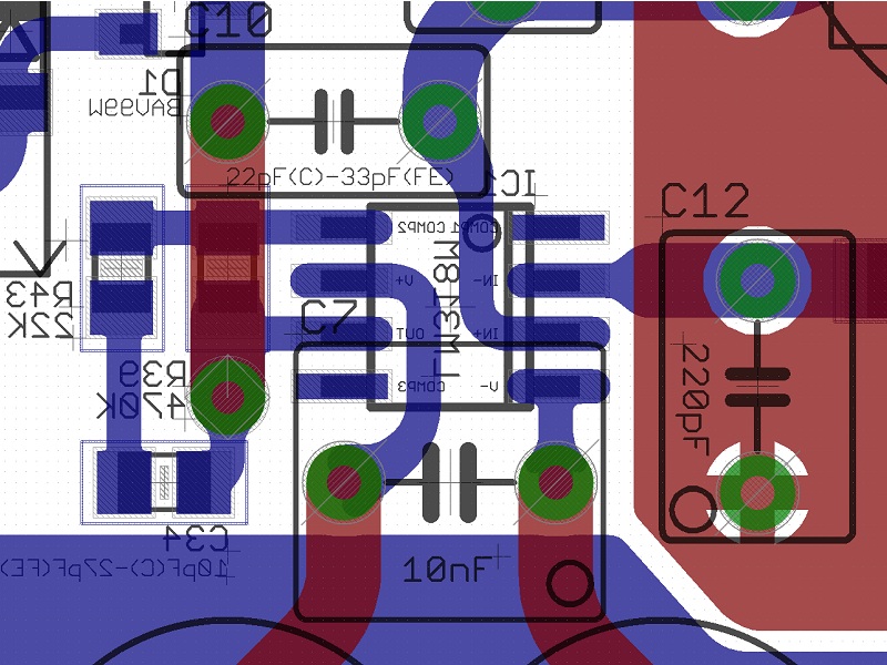
Andrew, the routing that Dario has adopted is nearly optimal. You have not taken into account that the LM318 is SMD, so it is not possible to place C7 between its power pins on the same layer. If you put it on the other layer, the two vias will between them consume 3.2 mm of trace length and create transmission-line discontinuities at the potentially four locations, causing reflections, standing waves, etc.I can see that an smd capacitor directly between the two opamp power pins can have a trace length of far shorter than the circuitous route shown in your accompanying extract.
Give me a ruler and a PCB and I will measure the difference. Possibly of the order of 40% to 50% of the route you have adopted.
For a through-hole FKP2, the FE routing as shown is as good as it gets. You can maybe shave off about 1mm (about 0.5 nH trace inductance) by moving the C7 pads closer, but it may also violate pad-to-pad minimum clearances for most PCB fab houses.
Edit: The only change that I would suggest is extending the small-signal lifted-ground plane below the LM318 on the other side of the PCB, at least to shield the signal traces.
Last edited:
Hello guys! I've made 5 years ago 3 Mauro Penasa My Ref chip amp's. I have experimented with different power supply and different components on the amp. I did not followed this thread since then. Plese tel me what developments have appeared in the mean time, if there is any important upgrade over the original.
Thanks!
Thanks!
Last edited:
Siva, did you ever find a LM3886 spice model that you can trust?
Bob - nope, the official model released by TI earlier this year turned out to be badly broken. They then released an updated TINA model, but it's encrypted, so there's no easy way to convert it to SPICE, and in any event, it's not clear that the TINA model fixes problems that were found in the earlier SPICE model.
Where is the science to support this preposterous conclusion?
In reality... maybe
")
If you would have considered that, as Siva noted (thanks, Siva
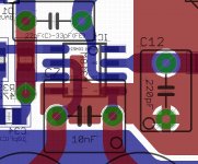
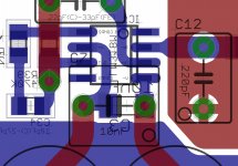
), the LM318 is a suface mounted part it would have been perfectly clear that there's no much difference.For your convenience I've added a 1206 C7 to compare lenght, it's less than 1mm...
That is a 0.183735nH more (calculated using this calculator).
Let's assume the total lenght of the left trace is 5.5mm (1.242368nH), the difference is less than 15%.
I see your Eagle PCB layouts have nice smooth transformation from thin traces to large pads. Did you use brute force or does Eagle PCB have the feature?
Hi George,
Eagle can't do it automatically but you can draw those smooth transofrmation pretty easily with Eagle.
Edit: The only change that I would suggest is extending the small-signal lifted-ground plane below the LM318 on the other side of the PCB, at least to shield the signal traces.
I've considered it but the plane to be used would have been the 0V (signal ground).
I've had the doubt that some coupling would have been possible so I've dropped it, just to be safer.
I did not followed this thread since then. Plese tel me what developments have appeared in the mean time, if there is any important upgrade over the original.
Mauro didn't made further public upgrades (there's the My_EVO -Evolution, not public).
I did a My_Ref variation which includes a completely redesigned PCB, new PS, different grounding and compensation.
You can read about it:
http://www.diyaudio.com/forums/chip-amps/197120-my_ref-fremen-edition-need-help-pcb-evaluation.html
http://www.diyaudio.com/forums/chip-amps/207390-my_ref-fremen-edition-beta-build-fine-tuning.html
http://www.diyaudio.com/forums/chip-amps/216915-my_ref-fremen-edition-rc-build-thread.html
IMHO it's a clear improvement
Attachments
Last edited:
Not me. You can perceive difference where there is none, as dozens of psychology experiments will demonstrate.The differences being heard by some members tells me the signal is being changed in their implementations.
Not me. You can perceive difference where there is none, as dozens of psychology experiments will demonstrate.
PLEASE! PLEASE - DON'T BRING THAT ARGUMENT HERE!!!!
While your viewpoint is respected, we have not been burdened by that endless and pointless circular CF and would like to keep it that way. If we are ignorant of the volumes of pertinent scientific studies - please let us wallow in that shortcoming. Too many threads have been destroyed once that controversy is introduced.
Respectfully - PLEASE!
I don't mind much if people remain ignorant. And no one has to respond. But I don't think any viewpoint, my own included, should be suppressed for the sake of not disturbing the peace.PLEASE! PLEASE - DON'T BRING THAT ARGUMENT HERE!!!!
While your viewpoint is respected, we have not been burdened by that endless and pointless circular CF and would like to keep it that way. If we are ignorant of the volumes of pertinent scientific studies - please let us wallow in that shortcoming. Too many threads have been destroyed once that controversy is introduced.
Respectfully - PLEASE!
And my claim isn't controversial, it is very easy to demonstrate.
Wait! Was your post satire?
No Sir, My comment was serious. Please note that I used the word respect twice in my message. I am simply stating the fact I have participated in at least three threads in the last two years where the identical positions - both pro and con - dealing with whether one can give credibility to what is heard/perceived are expressed. They all have decayed into personal snipes and dogma, again pro and con, and nobody's position ever seems to budge.
It is a very interesting area to investigate (just watched another series on how the mind can trick us last night - Discovery CH.) but consumes enormous amounts of time that I believe could be put to better use. Please believe that my comments are not a personal swipe at you and/or your body of knowledge specifically. I respect and enjoy science, but attempt to keep it within a usable perspective in matters artistic. In the end the technology is there solely to support a valuable and loved form of art - Music.
My hope is simply to avoid the clutter.
Last edited:
In reality... maybe
If you would have considered that, as Siva noted (thanks, Siva
For your convenience I've added a 1206 C7 to compare lenght, it's less than 1mm...
That is a 0.183735nH more (calculated using this calculator).
Let's assume the total lenght of the left trace is 5.5mm (1.242368nH), the difference is less than 15%.
Dario,
What numbers were you using for the trace width and trace thickness, for the inductance calculator? The inductance figures seem quite low.
Also: Is this Mauro's original PCB layout? I think you mentioned whose it was, actually. I seem to remember Mauro allowing someone to produce and sell copies of his first layout. So maybe this is that one. Please forgive me, but I am unfamiliar with what versions and "spin-off" versions of the MyRef are in existence. If this one is "frozen" for no more development, or is out-dated, then I might not want to keep bothering you and Siva about it. It might be like stumbling in through the back door of a famous ancient cathedral and excitedly engaging the nearest priest in a discussion of changes to the architecture that I thought were needed.
Can you or someone please post links to the relevant threads for each of the major MyRef versions and spin-off versions or closely-related circuits? I think that I am finally ready for another project to build.
Thanks.
Tom
I agree we should just discuss the technical aspects. What people can hear and how it is described contain too many variables to talk about.
Roger that! And I concur.
We should just respect the personal capabilities of individuals.
Or at least we should respect the fact that they are widely variable, and agree that we don't want to try to reconcile them (or even think about them), here.
- Home
- Amplifiers
- Chip Amps
- My "audiophile" LM3886 approach