I accidentally shorted the outputs of one channel, for a quick estimate of the damage, am I just looking at a bad LM3886? I was under the impression that these were short protected. Did not smell anything.
Hmm. the relay is not turning on now.
The first thing to check is the 1 Ohm resistor.
If it's good either the LM3886 or LM318 could be burnt (LM318 first).
see, If I had sent you mine you could be cannibalzing it right now 
It's bad that this happened to you but sometimes problems can turn into possibilities; Maybe you can see what LM318H tastes like.
I haven't had time to work on my boards yet but if it's as you guess, the R11 1ohm 1/4W 1% and I can find it in my rural area I will be making my first Mouser order. I could get some things for you and send them to you ?
I've been reading the Ultimate BOM thread and would like to try some of the substitutions.
Have you guys found a PSU for the LM318 yet ? There's much I don't understand but I wondered, if you can tap in to the My_Ref PS caps and use LM338 circuit to power a Lightspeed why can't it power a opamp ? Are there other considerations ?
Thank you guys for putting up with me while I learn.
I think you are right, I seem to be getting output voltage but not current, the 1Ohm R11 seems to be open.The first thing to check is the 1 Ohm resistor.
If it's good either the LM3886 or LM318 could be burnt (LM318 first).
Below is the original MyRef C on scope
Below is the original MyRef C on scope scaled up
Below is the MyRef C with Dario's compensation PMed to me (same input signal, just moved the probes to the other channel)
Below is a frequency/phase response comparison
The frequency and phase are improved, but it clips very early, and the gain is reduced. Although you see the level indicators up very high, I used the physical volume control in the sound card to reduce the output. Since my listening levels were quite low, probably I was just clipping the low frequency just a bit.
I will go back and do some more listening.
An externally hosted image should be here but it was not working when we last tested it.
Below is the original MyRef C on scope scaled up
An externally hosted image should be here but it was not working when we last tested it.
Below is the MyRef C with Dario's compensation PMed to me (same input signal, just moved the probes to the other channel)
An externally hosted image should be here but it was not working when we last tested it.
Below is a frequency/phase response comparison
An externally hosted image should be here but it was not working when we last tested it.
The frequency and phase are improved, but it clips very early, and the gain is reduced. Although you see the level indicators up very high, I used the physical volume control in the sound card to reduce the output. Since my listening levels were quite low, probably I was just clipping the low frequency just a bit.
I will go back and do some more listening.
Hi Soongsc,
so you have fixed the broken channel, fine!
In scope pictures you posted the upper waveform is input and lower output?
If so it seems that also the input is clipped... I can't understand....
Let us see your opinion
Are you sure that the fixed channel is behaving correctly?
To be sure I would swap compensation schemes between them.
I never noticed SPL differences between the two comps, I'll check again this evening with a SPL meter.
so you have fixed the broken channel, fine!
The frequency and phase are improved, but it clips very early, and the gain is reduced. Although you see the level indicators up very high, I used the physical volume control in the sound card to reduce the output. Since my listening levels were quite low, probably I was just clipping the low frequency just a bit.
In scope pictures you posted the upper waveform is input and lower output?
If so it seems that also the input is clipped... I can't understand....
I will go back and do some more listening.
Let us see your opinion
Are you sure that the fixed channel is behaving correctly?
To be sure I would swap compensation schemes between them.
I never noticed SPL differences between the two comps, I'll check again this evening with a SPL meter.
Sorry, I think I got the Channels mixed up, let me redo the measurements.
Below is the original MyRef C on scope
An externally hosted image should be here but it was not working when we last tested it.
Below is the original MyRef C on scope scaled up
An externally hosted image should be here but it was not working when we last tested it.
Below is the MyRef C with Dario's compensation PMed to me (same input signal, just moved the probes to the other channel)
An externally hosted image should be here but it was not working when we last tested it.
Below is a frequency/phase response comparison
An externally hosted image should be here but it was not working when we last tested it.
The frequency and phase are improved, but it clips very early, and the gain is reduced. Although you see the level indicators up very high, I used the physical volume control in the sound card to reduce the output. Since my listening levels were quite low, probably I was just clipping the low frequency just a bit.
I will go back and do some more listening.
OriginaL MyRef C TP BOM
MyRef C with Dario's compensation PMed to me.
It seems the original has better frequency and phase response.
This is much more consistent with what I would expect.
However, as I tried to continue the CRO display, it seemed that every time I powered up, the original channel (the one that died a while back) would have lower gain. I have no explanation for this.
An externally hosted image should be here but it was not working when we last tested it.
MyRef C with Dario's compensation PMed to me.
An externally hosted image should be here but it was not working when we last tested it.
It seems the original has better frequency and phase response.
This is much more consistent with what I would expect.
However, as I tried to continue the CRO display, it seemed that every time I powered up, the original channel (the one that died a while back) would have lower gain. I have no explanation for this.
As a temporary measure when you have no stock of compatible insulators:
Use a strip of wide sticky back thin plastic film. i.e 3M, Scotch tape, Sellotape.
These will give good low temperature electrical insulation and let Thermals pass through.
You will need the glossy, unglued face smeared in thermal goop.
Although these tapes do not have the high temperature performance of Mylar, Kapton and similar, they work well in prototype development, especially in the initial stages where everything is supervised and relatively cool.
I would not recommend this as a permanent solution even though I have successfully completed some very high temperature testing with unbranded tapes. eg. sink at >70degC and Tc~90degC for a 48hour soak test.
Last edited:
After retesting, both channels have the same gain, the phase response is the same as the last test. So now I will be testing my own feed forward compensation to see how things work out.
So in your measures the alternate comp is worse than the original...
Particularly on high frequencies... how can this lead to the sweeter highs, much bigger soundstage and tighter bass I'm hearing?
This is very confusing, first of all it could be some place in the electronics or speaker drivers may have inverted polarity. This is possible because generally inverted polarity operation in electronics produces less distortion. Some speaker crossovers also invert the polarity of drivers. Now, if this, combined with playing certain specific music, can sometimes just provide the right combination for best playback.So in your measures the alternate comp is worse than the original...
Particularly on high frequencies... how can this lead to the sweeter highs, much bigger soundstage and tighter bass I'm hearing?
Below is the results of listening through a few thousand CDs in regards to polarity, which was published in a Hong Kong audio magazine in 2000.
An externally hosted image should be here but it was not working when we last tested it.
This is about the only explanation I can come up with. But on my system, where I have full control of speaker phase performance and audio cable performance, the results match my listening impression.
My other reference is an active speaker equalized with Ultimate Equalizer from Bodzio Software. This active speaker uses a very traditional chip amp design for the LM3886, the only difference is that a 5Ohm resistor is in series with this plus some impedance flattening circuits. My goal is to use the MyRef type design of a current pump to beat the active speakers. With and without using Ultimate Equalizer.
One thing I discovered is that when the system phase is flat, then the difference between polarity is significantly reduced.
Last edited:
This is very confusing, first of all it could be some place in the electronics or speaker drivers may have inverted polarity.
...
One thing I discovered is that when the system phase is flat, then the difference between polarity is significantly reduced.
I've just listened to a Chesky Record CD, that according to the posted list should be in phase, while most of the CDs I usually use are 180°.
The differences between the two comp where exactly the same to my ears with both types of CDs.
But, maybe, I have identified which component produce such phase differences Vs a plain gainclone: C32
This compensation cap obviously acts also like a filter.
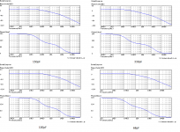
Using this calculator I've obtained the attached graphs which are coherent with your measurements.
The use of that calculator is, IMHO, appropriate since the LM318+LM3386 can be considered a single opamp used in non-inverting configuration.
According to those graphs also the sweeter highs can be explained, in fact they're attenuated...
BTW I've tried to lower til 100pF C32 maintaining the others 'alternate' values and the amp works but I can't say nothing about stability.
With 100pF in C32 it seems to sound best but I should further evaluate.
Siva, can you make some sims on a lower value C32?
Attachments
Last edited:
I think in my simulation, C32 does effect the frequency and phase. I will have to check, but I recall removing it produced better phase. I think that was in my first sim.
I don't think removing it completely it's a good idea, it was introduced with RevB and mantained in RevC and I think it's needed to ensure stability...
Take a look to the graphs from this post...
Last edited:
- Home
- Amplifiers
- Chip Amps
- My "audiophile" LM3886 approach