Nidhogg said:The italian site shows how to solder the components
Hi Nighogg - you almost certainly have dry joints - I can see them from your photos
Get your iron nice & hot and remelt each joint until the solder flows evenly onto the pad & wire - this should only take about 2 - 3 seconds per joint - a little extra solder may help this.
After a while you will know how it should look because a good joint looks neat & clean.
good luck
mike
Nidhogg said:
Thanks for your help !
J.
Hi,
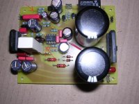
Well you most major problem was the incorrect trafo wiring, you wanted to wire the secondaries in series and then take the center (where you hoined them) as your power GND.
The second thing which could ave maybe save your chip (and you should always have connectd) is the jumper to the speaker protection circuit.
See the red arrows on the attched editied photo.
Hope the road goes more smoothly for you now.
Cheers!
Russ
Attachments
Thanks for your answers !
Of course now that I think about it it seems quite obvious that all those resistors could not have been put there for nothing and without jumpers they sure aren't very useful... I guess that's what you get for not trying to understand how things work
Just to be sure could you confirm that the jumpers are :
- J1
- PAD2 <-> PAD3
- PAD1 <-> PAD4
- O_SP <-> OUT SP2
I'll fix this, correct the trafo wiring, resolder the dodgy joints and see if the lm3886 is really toast or not. If not ... well I still have 4 channels worth of parts to burn")
The boards were etched by a guy on a french forum who offered to do this for a small fee. Apart from a few holes that were too small, they sure look good !
Thanks again.
J.
Of course now that I think about it it seems quite obvious that all those resistors could not have been put there for nothing and without jumpers they sure aren't very useful... I guess that's what you get for not trying to understand how things work
Just to be sure could you confirm that the jumpers are :
- J1
- PAD2 <-> PAD3
- PAD1 <-> PAD4
- O_SP <-> OUT SP2
I'll fix this, correct the trafo wiring, resolder the dodgy joints and see if the lm3886 is really toast or not. If not ... well I still have 4 channels worth of parts to burn
The boards were etched by a guy on a french forum who offered to do this for a small fee. Apart from a few holes that were too small, they sure look good !
Thanks again.
J.
Nidhogg said:
- J1
- PAD2 <-> PAD3
- PAD1 <-> PAD4
- O_SP <-> OUT SP2
Your Welcome.
You are correct. Same of the jumpers (PADS 1-4) fit best under the PCB.
Cheers!
Russ
It's working ! 
I can't believe it, those chips sure can take a beating. I made sure I didn't power it up for more than a few seconds each time but still, wrong power supply wiring, no protection, a nasty short, burn marks and it's still working !
I measured DC output offset but I read 0.00mV. Is that possible ? Did I measure it wrong ? (between OG and OUT, DC 200mV position on my multimeter, with or without a source).
Anyway I couldn't wait ... I plugged some old JVC speakers to test it and sound is coming out perfectly, loud and clear
Thanks again for your help, I'll go solder those other 4 channels now
J.
Nidhogg said:It's working !
J.
Excellent news!!!
I knew you could do it. Let us know how things contnue to work out. Its funny, I look at the old PCB (one of the first I did) and I have to shudder. I have learned a lot since then
I am glad it is working for you.Cheers!
Russ
why not try to design an hybrid "MyREF"-like amplifier?
if you add a tube buffer, make sure you add/move your volume control before the buffer, and avoid the use of an (unneeded) preamplifier before it.
BTW: if you want to go for a tube, rather than just adding a tube buffer/preamplifier in front of the whole amp as is, I would rather try to re-design an hybrid amplifier around the DeParavicini/Penasa concept. That is: replace the LM318 with a tubed "VAS"!
(remove the LM318 voltage gain stage and design an appropriate tube-based gain stage to replace it).
If I remember correctly, you need about 9V at the input of the current pump for full output power. That's an easy task for any tube, but you need quite some gain to allow for enough overall NFB (to bring the overall output impedance back to some decent value, let say at least <= 1 ohm).
Moreover, for the current pump to work as intended, the output impedance of the new "VAS" must have an output impedance close to the (open loop) output impedance of the LM318 (how much is it?).
Alternatively, the resistance on the current pump "input" which sees the lower impedance must be increased to keep the bridge balanced (both "inputs" of the bridge must see about the same impedance).
To get enough gain using triodes you'll likely need at least a couple of stages. And you'd probably want to use a low noise tube (such as 12AX7 or better yet a 6S45Pi [6С45ПE]) at the input.
Given the small signal amplitude involved, even a couple of simple resistor loaded grounded catode stages should be fine (and very linear, too). Or perhaps just one stage can be enough if using some good, hi-gain pentode. After all, it will be inside an overall NFB loop.
BTW, I would limit the overall loop gain, use all of the "VAS" gain for NFB and add another (mid-mu) tube as an input buffer and preamplifier outside of the loop.
It's not trivial, but it's doable... and I would say it's probably something quite interesting to try out! ...would do it myself, but have no time to.
Anyone interested in trying this out?
BrianDonegan said:If I find some time, I'll try the valve buffer. Seems easy enough.
if you add a tube buffer, make sure you add/move your volume control before the buffer, and avoid the use of an (unneeded) preamplifier before it.
BTW: if you want to go for a tube, rather than just adding a tube buffer/preamplifier in front of the whole amp as is, I would rather try to re-design an hybrid amplifier around the DeParavicini/Penasa concept. That is: replace the LM318 with a tubed "VAS"!
(remove the LM318 voltage gain stage and design an appropriate tube-based gain stage to replace it).
If I remember correctly, you need about 9V at the input of the current pump for full output power. That's an easy task for any tube, but you need quite some gain to allow for enough overall NFB (to bring the overall output impedance back to some decent value, let say at least <= 1 ohm).
Moreover, for the current pump to work as intended, the output impedance of the new "VAS" must have an output impedance close to the (open loop) output impedance of the LM318 (how much is it?).
Alternatively, the resistance on the current pump "input" which sees the lower impedance must be increased to keep the bridge balanced (both "inputs" of the bridge must see about the same impedance).
To get enough gain using triodes you'll likely need at least a couple of stages. And you'd probably want to use a low noise tube (such as 12AX7 or better yet a 6S45Pi [6С45ПE]) at the input.
Given the small signal amplitude involved, even a couple of simple resistor loaded grounded catode stages should be fine (and very linear, too). Or perhaps just one stage can be enough if using some good, hi-gain pentode. After all, it will be inside an overall NFB loop.
BTW, I would limit the overall loop gain, use all of the "VAS" gain for NFB and add another (mid-mu) tube as an input buffer and preamplifier outside of the loop.
It's not trivial, but it's doable... and I would say it's probably something quite interesting to try out! ...would do it myself, but have no time to.
Anyone interested in trying this out?
Member
Joined 2003
To measure DC offset the input must be shorted to ground. 0mV is very possible, it is usually a very small offset of only a few mV.Nidhogg said:I measured DC output offset but I read 0.00mV. Is that possible ? Did I measure it wrong ? (between OG and OUT, DC 200mV position on my multimeter, with or without a source).
Glad to hear you have things sorted out.
As I said Russ, it changes the Rev C into a beast... And I used the simplest Valve buffer ECC88 circuit I could find.
It is kind of freaky how much resolution it adds to sounds, with vocals haveing much less fricative and explosive sounds, its kind of like upping the resolution on a monitor the edges becomes smoother... I think the word people sling around casualy is RELAXED.
I gotta call Willward again to go listen to his Valve hybrid system for comparison, but I think the REV C is now much closer to his leage than before... and EXTREMELY impressive for the pricepoint combined with the buffer.
Nordic, could you please describe your solution with ECC88 a little bit in detail? I have built MyRevC, I like the sound a lot, but the tube sound attracts me too. I even have some E88CC, and perhaps the +/-35V supply could suffice for these tubes. I am really excited about this.
Buffer
Nordic,
You might want to try the ad815 as a buffer. I have a couple tube buffers, 6DJ8, 12BH7, and 6080. The AD815 bests all three.
It transformed the sound in my system. More extended, tight bass. It also revealed unheard flaws in the sources. Used to think my disc player sounded fine after 10 minutes. Now there is a little sharpness, and it rounds out after about an hour.
George
phofman said:Nordic, could you please describe your solution with ECC88 a little bit in detail? I have built MyRevC, I like the sound a lot, but the tube sound attracts me too. I even have some E88CC, and perhaps the +/-35V supply could suffice for these tubes. I am really excited about this.
Nordic is actually talkin about a completely different amp. This one here:
http://www.diyaudio.com/forums/showthread.php?postid=762618#post762618
"REV C with Fran'z valve buffer"
Franz's amp is a tube buffered LM3875. I have that one also. I "believe" Nordic took the tube board section and just made a buffer for his Rev_C. It would be VERY difficult to integrate the tube into the circuit instead of the LM318 UNLESS you are very skillful. I belive it was just mentioned in a recent post, but it's not something I would attempt without a thorough inventory of test equipment.
Edit: It was UnixMan who explained how to swap opamp for tube. It was a good write up .
But I personally will stick to what the designer had intended as thanks to Mauro for his time and gift. It has really brought me many hours of joy... Thanks to Brian and Russ for the kits too.
Franz's amp is a tube buffered LM3875. I have that one also. I "believe" Nordic took the tube board section and just made a buffer for his Rev_C. It would be VERY difficult to integrate the tube into the circuit instead of the LM318 UNLESS you are very skillful. I belive it was just mentioned in a recent post, but it's not something I would attempt without a thorough inventory of test equipment.
Edit: It was UnixMan who explained how to swap opamp for tube. It was a good write up
.But I personally will stick to what the designer had intended as thanks to Mauro for his time and gift. It has really brought me many hours of joy... Thanks to Brian and Russ for the kits too.
Sorry for mentioning that question one more time but I have read the Mauro's paper, and Russ's post #2134 and it is still not clear to me what makes the input impedance 100k, and not 3k3, as far as the (-) input of the OPAmp is a low-Ohm one.
Can somebody please explain that to me? Thanks!
Can somebody please explain that to me? Thanks!
Asen said:Sorry for mentioning that question one more time but I have read the Mauro's paper, and Russ's post #2134 and it is still not clear to me what makes the input impedance 100k, and not 3k3, as far as the (-) input of the OPAmp is a low-Ohm one.
Can somebody please explain that to me? Thanks!
Read this post and the next several to answer your question:
http://www.diyaudio.com/forums/showthread.php?postid=697230#post697230
especially this post:
http://www.diyaudio.com/forums/showthread.php?postid=698036#post698036
- Home
- Amplifiers
- Chip Amps
- My "audiophile" LM3886 approach