Hi enter,
Congrats on your completion of a BIG project.
I am relieved to have (carefully) completed two mono rev c boards, so I can appreciate the work involved in building a 5.1 amp. From all reports, Mauro's rev c amps will make the effort worthwhile. You probably now have the best 5.1 amp in town.
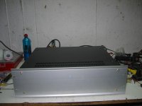
You will need to leave the cover off when playing, for ventilation. Some vent holes in the sides would help also. If you did this you could vent the cover and then be able to leave it on.
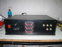
I guess you went for the spring clip speaker terminals for economy and convenience.
Regards,
Audie.
Congrats on your completion of a BIG project.
I am relieved to have (carefully) completed two mono rev c boards, so I can appreciate the work involved in building a 5.1 amp. From all reports, Mauro's rev c amps will make the effort worthwhile. You probably now have the best 5.1 amp in town.
You will need to leave the cover off when playing, for ventilation. Some vent holes in the sides would help also. If you did this you could vent the cover and then be able to leave it on.
I guess you went for the spring clip speaker terminals for economy and convenience.
Regards,
Audie.
Thanks a lot for your kind words and your advise as well.
About the chassis i had this in mind to open some holes on top and sides of it so the heat goes out from ther but i havent tested it yet with all chanels working hard to tell you for shure.With the 2 front chanels playing in full mode there is no problem.
I dont think useing something else for the speaker terminals will make a audible difference so way spenting more money
enter wrote: I don't think using something else for the speaker terminals will make an audible difference, so why spend more money
Agreed. You are the best person to make that call.
Many people consider spring clip speaker terminals do not make a good connection with the speaker wire. They are fiddly to use and usually only accept up to 14 gauge bare wire, so terminated audiophile cables cannot be used.
Some also believe that good connections are necessary to preserve signal integrity. The thought is that good connections will not degrade the signal, wheras poor connections will degrade the signal, which in a system with good resolution, will be audible.
In a typical PC based system it may be that the resolution may be insufficint to reveal audible differences between connectors.
It's all very subjective. Different people will have different experiences of the effect of connections, as they will of other components.
Regards,
Audie.
Byrd said:Honestly if I could afford the time I don't think I would be running any commercial equipment. Pthew.")
I am in your camp.
My goal is to eventually eliminate those things which I did not have a hand in creating from my collection.billabong said:Hi enter,
You might have to wait for warmer weather to access your amplifier ventilation requirement.
I see that the temperature in Athens is 5C today!
Audie.
Audie.
Hi billabong
Know problem this days.The major problem will start at summer days
Russ White said:Enter,
Nice amp man. I wouldn't worry much about the speaker terminals, especially for your intended application. Just enjoy it.
Cheers!
Russ
Hi Russ
Thanks, as for your pcb design with rev_c i won't say
what already handreds and man many more people have sayed about the excellent job you diid

Input caps - MKPT, Teflon and now PIO
I tweaked my Mauro MyRef. Rev. A recently and thought I'd mention the improvements. I had been using a single 1uF Multicap MKPT bypassed with a Russian .1uF Teflon cap in series with each input RCA. I added in another 1uF Russian PIO to parallel the others. Now I have around 2.1uF and a witches brew of different caps. The mixture added a bit of body, but the detail is still excellent. I like the improvement a lot.
I just fixed up my Kookaburra preamp after problems and have it feeding the Mauro amp. I put the Kookaburra in another box, so I can move it around to different amps. The sound I'm getting is very nice. Great detail, PRAT and a tad bit of warmth. I knew the amp would take a while to be fully burned in and I think I'm just now seeing the entire virtues of this amp.
BTW, I'm feeding 90db efficient Merlin VSM-MM with SuperBAM with this modest amp/preamp and it's doing a bang up job.
Thanks again Mauro, Russ and Brian. I've learned quite a bit on this project.
If I remember right some guys on here were talking about making the opamps on this amp work in class A. This site has a few different ways to do this.
http://tangentsoft.net/audio/opamp-bias.html
Has anyone used some JFETs to try this????
http://tangentsoft.net/audio/opamp-bias.html
Has anyone used some JFETs to try this????
Did not help for me
I used a temperature cooefficient diode, forget the number to bias it up to about 12 ma or so. The sonics were degraded. Took them out.
My take on this circuit is that improving the power supply through better transformers, diodes, capacitors, and wiring are the path to better results. But I am happy with my stereo version using standard quality parts. Next one will get an upgrade in these areas.
It will get battery power for the opamp. This will lower the amount of heat generated by a bunch. I saw that four chassis ASR Emitter and want something close. It has three power supply chassis.
George
Hi everyone!
After reading this thread I was inspired by Mauro’s design and put together 3 monoblocks for my 3-way DIY loudspeakers. I compared the sound to another four different GC designs and found this one to be the best so far (thanks, Mauro). I made the monoblocks on my own PCB design, which follows very closely Mauro’s layout.
Everything seems to work fine except one thing: LM318 (in metal can package) are running hot, even with no signal and no load. I have some DIY amplifier building experience, so the first thing I did was to check for oscillations with 100MHz oscilloscope. I could not see any oscillation anywhere in the whole frequency range of the oscilloscope. After playing a couple of CDs with the load connected, the LM318s heated up to approx 60-75C while LM3886s where just slightly warm. I have checked all parts and connections on the board, bypassed all caps and did a lot of other things with no positive results.
Can anybody tell me what is the operating temperature of LM318 should be? And if what I see is normal, than why this is happening?
This thing is puzzling me for several days; I lost my appetite and cannot sleep at night , please help.
Thanks.
After reading this thread I was inspired by Mauro’s design and put together 3 monoblocks for my 3-way DIY loudspeakers. I compared the sound to another four different GC designs and found this one to be the best so far (thanks, Mauro). I made the monoblocks on my own PCB design, which follows very closely Mauro’s layout.
Everything seems to work fine except one thing: LM318 (in metal can package) are running hot, even with no signal and no load. I have some DIY amplifier building experience, so the first thing I did was to check for oscillations with 100MHz oscilloscope. I could not see any oscillation anywhere in the whole frequency range of the oscilloscope. After playing a couple of CDs with the load connected, the LM318s heated up to approx 60-75C
while LM3886s where just slightly warm. I have checked all parts and connections on the board, bypassed all caps and did a lot of other things with no positive results.Can anybody tell me what is the operating temperature of LM318 should be? And if what I see is normal, than why this is happening?
This thing is puzzling me for several days; I lost my appetite and cannot sleep at night
, please help.Thanks.
lumumba_p said:Everything seems to work fine except one thing: LM318 (in metal can package) are running hot, even with no signal and no load. I have some DIY amplifier building experience, so the first thing I did was to check for oscillations with 100MHz oscilloscope. I could not see any oscillation anywhere in the whole frequency range of the oscilloscope.
Years ago I used an LM318 in an IM analyzer and had a lot of
difficulty with stability at high rail voltages. At low rail voltages
it worked fine, but at more than about 10 volts it had high
distortion and noise, which I now attribute to internal high
frequency instability, although like you I couldn't see it on my
scope.
This is common with high open loop op amps run at low gain.
Take a look at the "7 Easy Pieces" on the Pass Labs forum,
where you can throw away some feedback by loading the input
terminals on inverting and noninverting op amp circuits.
Nelson Pass said:
Years ago I used an LM318 in an IM analyzer and had a lot of
difficulty with stability at high rail voltages. At low rail voltages
it worked fine, but at more than about 10 volts it had high
distortion and noise, which I now attribute to internal high
frequency instability, although like you I couldn't see it on my
scope.
This is common with high open loop op amps run at low gain.
Take a look at the "7 Easy Pieces" on the Pass Labs forum,
where you can throw away some feedback by loading the input
terminals on inverting and noninverting op amp circuits.
I have run the National 8 pin dips in mine at 17 volts with no problems. They do not even get warm. Guess the feedback loop is keeping it in an optimal range.
George
- Home
- Amplifiers
- Chip Amps
- My "audiophile" LM3886 approach