thats my readily finished opa 549 amp, built quite differently from the gainclone trend. .that is: 200VA +IXYS screw terminal bridges (320A peak) + 44000uF for each channel in a dual mono config.. sounds really good.. and features considerable bass extension and volume.. imaging is really beyond critic, with acurate represantation of depth, heidth, and width.. detail to the most.. really satisfactory result..
An externally hosted image should be here but it was not working when we last tested it.
heres another one
An externally hosted image should be here but it was not working when we last tested it.
and yet another..
An externally hosted image should be here but it was not working when we last tested it.
Hooray! Let's hear it for good engineering sense in amp construction!
My LM3886 amp has 108,000 uF (4x 27,000) in the power supply and it sounds fantastic. At these voltages capacitors are cheap. If you want decent bass, you need a stiff power supply.
You might want to go to PCBs as they will prevent things from moving around and possibly shorting with disastrous results. Otherwise, keep up the good work! I recently replaced my hay-wired LM3886 stuff with PCBs and now I rest a little easier...
I commend you!
I_F
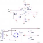
theres no schematic.. its simply a 549 in non inverting topology with a gain of 4,9, set with 1k & 3k9 resistors.. no input cap - you see, its not needed, with 5 mV of offset - bypassed with 470u elna starget at the crimped juction at the supply pins, with a bus ground topology on the chip, connected with an ample gauge to the star ground.. i prefer hard wired on those easy circuits, coz its easier to make contacts really heavy duty.. im happy to see people are using some SERIOUS capacitance at the psu.. and i ve tried it with 1000u, and its not worth the fuss.. in contradiction, this setup, (with heavy duty psu and cabling) sounds much more serious and real - accurate to me... im using 2x22000uF 63v per channel (nippon chemicon u32d), and dont think theres a better at the range for this one (was also using rifa and it just didnt sound right - bit too dry), except maybe for the nice elna for audio caps, that are in the same league, maybe a bit more laid back and warm...
costiss said:theres no schematic.. its simply a 549 in non inverting topology with a gain of 4,9, set with 1k & 3k9 resistors.. no input cap - you see, its not needed, with 5 mV of offset - bypassed with 470u elna starget at the crimped juction at the supply pins, with a bus ground topology on the chip, connected with an ample gauge to the star ground.. i prefer hard wired on those easy circuits, coz its easier to make contacts really heavy duty.. im happy to see people are using some SERIOUS capacitance at the psu.. and i ve tried it with 1000u, and its not worth the fuss.. in contradiction, this setup, (with heavy duty psu and cabling) sounds much more serious and real - accurate to me... im using 2x22000uF 63v per channel (nippon chemicon u32d), and dont think theres a better at the range for this one (was also using rifa and it just didnt sound right - bit too dry), except maybe for the nice elna for audio caps, that are in the same league, maybe a bit more laid back and warm...
a schematic would really help for us non-elecrical engineering types
")
heres the schematic...
i dont use fuses, coz the best contact is no contact.. that is, i didnt mean to havent even more series resistance on my supply rails.. 320A is the rectifiers peak current capacity.. the psus peak current capacity is about 30A.. i dont worry about speaker protection.. i dont use a pcb, coz i think its a better solution (and more pure) for such circuits... i have a series resistance, on the supply rails from the bridge to the chip, less than 20mOhms..
i dont use fuses, coz the best contact is no contact.. that is, i didnt mean to havent even more series resistance on my supply rails.. 320A is the rectifiers peak current capacity.. the psus peak current capacity is about 30A.. i dont worry about speaker protection.. i dont use a pcb, coz i think its a better solution (and more pure) for such circuits... i have a series resistance, on the supply rails from the bridge to the chip, less than 20mOhms..
Attachments
this was meant to be an ampplifier to get out the most from the 549.. im perfectly standing on my two feet... until i set out for my ref monoblocks (with discrete offcourse).. i really liked your 540/9540 circuit... why didnt you use some (much more linear) sk1058 n sj162..
To Costiss : I had both ones ( with lateral and vertical mosfets ). With lateral was distortiom at 20 kHz 0.003 % and with vertical 0.005 % ( 1 dB below clipping ) , at lower fr. was the same ( 0.0015 - 0.002 % ). Sound was better with vertical ones, mainly at bass, 'cos they have higher Ids.
It was THD, measured with BW up to 80 kHz ( on Ap ). Any so called complementary mosfets haven't in both polarity the same parametres. Remember, that distortion was measured 1 dB bellow clipping ( ! ), at lower levels was bellow noise, which is more than 120 dB bellow full power.
costiss - I not see the shematic image. Please send to me, felnavarro@gmail.com thanks
- Status
- This old topic is closed. If you want to reopen this topic, contact a moderator using the "Report Post" button.
- Home
- Amplifiers
- Chip Amps
- my view on a 549 amplifier (photos)