I just got done fixing my GC (thanks to all you who helped), and now it can output at much higher volumes. I had R1 and Rnfb reversed, so, 1x signal amplification, D'oh!!!
However, there seems to be a different problem:
Speakers are 91 db sensitive, 8ohm , MTM, two 5.25 drivers, 2 mids and one dome tweeter, rated at 100W
rectified voltage is around 34 volts, 330va supply (Avel Toroid)
Measured SPL from about 1 meter peaks around 93-94 db in room, and then the distortion will occur.
It really is promient on a punchy midrange/lower midrange notes. I turn it down as soon as I detect it though, never prolonged.
Before this distortion though, it sure does sound nice!
I have no reason to believe that my speakers are affected, but, its not out of the realm of possibility.

That was my first thought as well.What caps?
~50W should give plenty o´ beats with 91dB speakers.
Realize then snubberize.
")
joensd said:
That was my first thought as well.
~50W should give plenty o´ beats with 91dB speakers.
Realize then snubberize.
Indeed.
But 91db "quoted" sensitivity only says that they can play loud.
Loud doesn't always mean good.
It has to be LOUD AND CLEAR. (c) tbla.
They can still be a tough load for an amp, if they have big impedance dips in the bass.
Very common these days...
Sorry, I'm using the basic lm3875 from www.chipamp.com, 1500 uF 50v Panasonic FC Capacitors.
Here are the speakers:
Atlantic Technology 371 LR
Specifications
Manufacturer's Suggested Retail Price $1,499.00
Type Sealed-box, 3-way D'Appolito
Frequency response 80Hz - 20kHz +/- 3dB
Driver complement 1'' silk dome tweeter, two 3.5'' midrange, two 6.5'' woofer
Nominal impedance 8 ohms
Sensitivity 91dB
Recommended amplifier power 100 - 200W RMS
Cabinet finishes -
Dimensions 7.5''W x 23.65'' x 11.375
Weight 27 lbs.
THX certification Yes
I have the parts to make the Zobel network, it came with the kit.
If the speakers have an impedance dip of let´s say 2Ohms it could indeed be the Spike protection kicking in causing distortion.
(let alone an 8Ohm speaker shouldn´t have a dip of 2Ohms; but well manufacturers quotes...)
I´d try more capacitance first (if you use 1000u for example).
Stick another 4700u or more on each rail and listen.
If it´s not that try to get an impedance graph of your speakers.
And then, well probably put another chip in parallel...
(but I don´t think you´ll have to)
drfrink24 said:Sorry, I'm using the basic lm3875 from www.chipamp.com, 1500 uF 50v Panasonic FC Capacitors.
Here are the speakers:
Atlantic Technology 371 LR
Specifications
Manufacturer's Suggested Retail Price $1,499.00
Type Sealed-box, 3-way D'Appolito
Frequency response 80Hz - 20kHz +/- 3dB
Driver complement 1'' silk dome tweeter, two 3.5'' midrange, two 6.5'' woofer
Nominal impedance 8 ohms
Sensitivity 91dB
Recommended amplifier power 100 - 200W RMS
Cabinet finishes -
Dimensions 7.5''W x 23.65'' x 11.375
Weight 27 lbs.
THX certification Yes
I have the parts to make the Zobel network, it came with the kit.
Just looking at this I say: naturally you have a bass as loose as a mad cow.
You need to go high capacitance PSU, snubberized.
And you must use the zobel.
Also, what speaker cabels are you using?
drfrink24 said:For speakercable, its just some stranded monster cable I had lying around.
Stranded?
You need the zobel.
in the MTM configuration the load impedance is nominally 4 ohms, so the output is current limited -- this will show up as a flag on the National Semiconductor interactive design tool:
http://www.national.com/appinfo/audio/files/Overture_Design_Guide15.xls
try limiting the supply voltage to +/- 26V, you are really cooking the chip with a 34V supply and a 4R load.
the heat sink should have a thermal impedance of 2.6 or less.
i don't know why a zobel would aid the situation -- it is really quite a lot less complex.
jackinnj said:i don't know why a zobel would aid the situation -- it is really quite a lot less complex.
There are several problems here.
Besides a very undersized PSU and a high voltage, there is a chip with direct output that may also be oscillating because of high(ish) capacitive cables and multi-way complex crossover speakers.
The picture is not pretty at all.
It doesn't cost much to try the zobel.
jackinnj said:in the MTM configuration the load impedance is nominally 4 ohms, so the output is current limited -- this will show up as a flag on the National Semiconductor interactive design tool:
http://www.national.com/appinfo/audio/files/Overture_Design_Guide15.xls
try limiting the supply voltage to +/- 26V, you are really cooking the chip with a 34V supply and a 4R load.
the heat sink should have a thermal impedance of 2.6 or less.
i don't know why a zobel would aid the situation -- it is really quite a lot less complex.
A few more details.
Specifically, I'm using this trans:
http://www.partsexpress.com/pe/showdetl.cfm?&DID=7&Partnumber=122-640
25v secondaries, 330va. The measured output from the rectifier is 38.6 volts. Not sure how I gained over 13v, unless they sent me the wrong model.
The heatsinks, while clipping, are cool, the chip is cool. I can make it distort right away if I want to.
I don't know where you're getting 4 ohm from, it says the speaker is rated at 8 ohm? Are you thinking that they actually dip 4 ohms? I'm a little confused on this one...
Thanks for your help! (and everyone elses too!)
carlosfm said:
There are several problems here.
Besides a very undersized PSU and a high voltage, there is a chip with direct output that may also be oscillating because of high(ish) capacitive cables and multi-way complex crossover speakers.
The picture is not pretty at all.
It doesn't cost much to try the zobel.
Carlos -- there aren't several problems -- there is one problem -- the voltage is too high for a 4 ohm load.
drfrink24 -- an MTM configuration puts two drivers in parallel -- you have two nominal-8 ohm loads in parallel which equals one 4 ohm load.
plug the parameters into National's design guide and you'll see what I mean.
akunec said:How can you be sure that the drivers aren't 16 ohms, making the total nominal impedance 8 ohms? I would never expect speaker manufacturers to quote what each driver's impedance is, only the nominal impedance of the system.
i can be sure, within the realm of reasonable certainty, that the drivers are 8 ohms each as that is what the thread-starter stated.
jackinnj said:
i can be sure, within the realm of reasonable certainty, that the drivers are 8 ohms each as that is what the thread-starter stated.
Actually, I think they are 8 ohms in total. I posted the entire specs of the speakers. I just looked at the sticker on the back of them, and it says "8 ohms nominal".
I apologize if I wasn't making this clear.
jackinnj said:Carlos -- there aren't several problems -- there is one problem -- the voltage is too high for a 4 ohm load.
There ARE several problems.
And that doesn't seem to be one of them.
Because:
Originally posted by jackinnj i can be sure, within the realm of reasonable certainty, that the drivers are 8 ohms each as that is what the thread-starter stated.
No.
The speakers are quoted 8 ohms, so I suppose they have 4 ohm drivers wired in series.
And btw the amp needs the zobel for anything different from the "normal" figure-of-eight cable and very simple speakers (like fullranges).
Stranded/crossed cables have high(er) capacitance.
I repeat: in most circumstances, with most cables, with most speakers, the amp needs the zobel.
Yes, in most cases bass tightens up when you insert the zobel.
With the values I recommended long ago.
Including the series resistors.
carlosfm,
Ok, I may try the zoble network, however, I need some really basic help here.
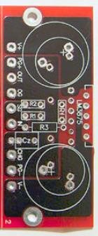
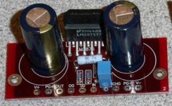
Brians boards come with a location, called Cz, you can see it in a picture I attached below.
The kit comes with two sets of extra components that are not mentioned in the instructions.
One pair of 3 ohm resistors and one pair of these blue, small, square blocks that I can only assume go where Cz is listed. They are marked with 100n GR 63v.
There is no +/- markings, nor a longer lead to indicate polarity.
How do I go about implementing a zoble network? I've done alot of searching, but, I seem to find more arguing than help...
Ok, I may try the zoble network, however, I need some really basic help here.
Brians boards come with a location, called Cz, you can see it in a picture I attached below.
The kit comes with two sets of extra components that are not mentioned in the instructions.
One pair of 3 ohm resistors and one pair of these blue, small, square blocks that I can only assume go where Cz is listed. They are marked with 100n GR 63v.
There is no +/- markings, nor a longer lead to indicate polarity.
How do I go about implementing a zoble network? I've done alot of searching, but, I seem to find more arguing than help...
Attachments
drfrink24 said:One pair of 3 ohm resistors and one pair of these blue, small, square blocks that I can only assume go where Cz is listed. They are marked with 100n GR 63v.
The resistors shoud be 2.7R, but 3R shouldn't make much difference.
drfrink24 said:There is no +/- markings, nor a longer lead to indicate polarity.
The 100nf cap doesn't have polarity, you can mount it either way.
drfrink24 said:How do I go about implementing a zoble network? I've done alot of searching, but, I seem to find more arguing than help...
Quite normal around here, unfortunately.
THD is high...
Read this:
http://www.diyaudio.com/forums/showthread.php?s=&threadid=39039&highlight=
- Status
- This old topic is closed. If you want to reopen this topic, contact a moderator using the "Report Post" button.
- Home
- Amplifiers
- Chip Amps
- Clipping GC?