Building brian gt lm3875 rev 3 stereo gainclone, with Avel 330va +-25volt tranny, expecting +-35vdc after power supply board rectification and filtering.
Have very small enclosure and want to use this power switch/LED "12V LED" combo, but not sure if I can drive this LED.
http://www.mouser.com/catalog/specsheets/PUSH-R13-523.pdf
This is the Mouser part, and it only says pushbutton switch, 3A 125Vac, 12V LED illumination. 3 amp should be just enough, but how to drive this LED - is it possible?
")
megajocke wrote:
True....but therez no reverse voltage here....LED is connected to DC...
LEDs don't like reverse voltages over 5 volts.. Put in an antiparallel diode or a diode in series...
True....but therez no reverse voltage here....LED is connected to DC...
Still puzzling LED circuit - not always so simple!
Thanks so much for helping. Still a puzzler though...
Is that a 6K ohm resistor? I dont understand why 1 watt is required, LEDs draw around 20 ma... Please clarify...
Since the switch includes the "12 volt LED", wouldnt that mean there is already a series resistor included in the device, chosen so that the led fires correctly with 12 vdc?
If so, wouldnt then choose a resistor that, together with the inclued resistor (series) would total 6k, or better yet try increasingly lower values until something around 20 ma is drawn...
Seems that datasheet is not detailed enough...
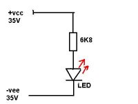
Re: Still puzzling LED circuit - not always so simple!
According to the picture above: 35+35=70V 70V/6.8k=10mA (LED current)
10mA x 70V = 700mW (the power dissipated in the resistor)
Hope it makes sense
Greg
ransom peek said:Thanks so much for helping. Still a puzzler though...
Is that a 6K ohm resistor? I dont understand why 1 watt is required, LEDs draw around 20 ma... Please clarify...
Since the switch includes the "12 volt LED", wouldnt that mean there is already a series resistor included in the device, chosen so that the led fires correctly with 12 vdc?
If so, wouldnt then choose a resistor that, together with the inclued resistor (series) would total 6k, or better yet try increasingly lower values until something around 20 ma is drawn...
Seems that datasheet is not detailed enough...
According to the picture above: 35+35=70V 70V/6.8k=10mA (LED current)
10mA x 70V = 700mW (the power dissipated in the resistor)
Hope it makes sense
Greg
Getting Closer but not there yet!
Thank Greggc (is that gc for gainclone?)! Now it's clear. It just didn't seem intuitive that a 1 watt resistor would be needed for an LED.
But, I still think there is likely to be a resistor inside the switch/led assembly that will be in series with the added resistor. So, I'll check it. If there is a resistor there, I think it wont work, because the spec sheet says 12 volt led, so at +- 35 vdc = 70 vdc, the current rating of the internal resistor will be exceeded. Now, an added series resistor will drop some of the voltage.
So I need to figure out the math on this one...
Another very simple, efficient method is to take a thin isolated wire and make 5 windings on your transformator. To be shure just measure the voltage that this 5 windings will supply. Works like a charm and does not have any adverse effects on any of the circuits (if it would at all, in some cases it is mentioned that leds coud have an audible effect if you place them on the supply rails, I have never been able to hear it though)
Indoubt has the answer
Hey thats really good! I'll add the windings to the toroid, check the voltage, and figure out the appropriate resistor. Wont need to special order the higher wattage resistor, just find one in my parts box.
Good, idea, tand simple solution! Thanks!
Oops! Hold on - then we'll have ac! Do we just let the led rectify it, so not to worry?
Ransom

Re: Getting Closer but not there yet!
Yes, GC is for gainclone....
If there is a resitor in ser. calculated for 12VDC inside the switch, then add another 56V/10mA=5.6k/1W or there about in ser. and connect it to 70VDC.
If you want to use AC add a parallel diode in the opposite direction to the LED, as suggested by megajocke, but you still need a res in ser. otherwise you;ll be shorting the windings in the oposite direction when the external diode is conducting.
Greg
ransom peek said:Thank Greggc (is that gc for gainclone?)! Now it's clear. It just didn't seem intuitive that a 1 watt resistor would be needed for an LED.
But, I still think there is likely to be a resistor inside the switch/led assembly that will be in series with the added resistor. So, I'll check it. If there is a resistor there, I think it wont work, because the spec sheet says 12 volt led, so at +- 35 vdc = 70 vdc, the current rating of the internal resistor will be exceeded. Now, an added series resistor will drop some of the voltage.
So I need to figure out the math on this one...
Yes, GC is for gainclone....
If there is a resitor in ser. calculated for 12VDC inside the switch, then add another 56V/10mA=5.6k/1W or there about in ser. and connect it to 70VDC.
If you want to use AC add a parallel diode in the opposite direction to the LED, as suggested by megajocke, but you still need a res in ser. otherwise you;ll be shorting the windings in the oposite direction when the external diode is conducting.
Greg
Re: Re: Getting Closer but not there yet!
Just a quick question about adding a winding. When calculating the resistance for the series resistor, do you use the ac voltage from the winding or should you multiply by 1.4 to get the effective dc voltage?
Newbie here so my terminology may be incorrect...
Thanks
Dave
GregGC said:
...
If you want to use AC add a parallel diode in the opposite direction to the LED, as suggested by megajocke, but you still need a res in ser. otherwise you;ll be shorting the windings in the oposite direction when the external diode is conducting.
Greg
Just a quick question about adding a winding. When calculating the resistance for the series resistor, do you use the ac voltage from the winding or should you multiply by 1.4 to get the effective dc voltage?
Newbie here so my terminology may be incorrect...
Thanks
Dave
Just a quick question about adding a winding. When calculating the resistance for the series resistor, do you use the ac voltage from the winding or should you multiply by 1.4 to get the effective dc voltage?
No, you only multiply by 1.4 if you use a full rectifier bridge after the transformer (and convert AC to DC).
When creating a supply for an LED, just wind say 10 turns around the transformer, apply power and measure the AC voltage. If it's too high, take away a couple of turns, measure again, and so on until you have around 2-3 volts.
No one knows why a reverse diode for an led?
Bill Fitzpatrick, please dont be so unkind in your post. If you are not interested in this thread simply dont follow it!
I am trying to learn something from the kind forum members that are sharing their experience. My foremost goal is not to build a gainclone and put it to use. It is to enjoy the experience of learning how to appreciate audio, learning diy building and theory, and exchanging ideas with others, most of whom are smarted than myself in the audio arena.
The bonus is the pleasure of using the end result, and perhaps comparing it to my recently restored Harman Kardon A50K tube amp and Harman Kardon HK385i. (compare a tube amp, a vintage solid state amp, and a brinagt gainclone).
My question is reasonable. A seasoned member recommended driving the LED with several turns of wire on the toroid, adding a series resistor, and a reverse parallel diode (reverse to the led).
I am not clear why one would add the reverse parallel diode and would like to understand, to be able to agree or diasagree, relative to the purplse of this diode.
Anybody know?
Re: Why a reverse parallel diode to the led driven by a few toroid tunrs?
LEDs don't like reverse voltage (in case you use AC). Adding a diode in reverse direction will prevent the LED from seeing rev. voltage higher than 0.7V which should be no problem for the LED. On the other hand your LED will blink with 30/25 Hz if you use separate windings from the transformer which may be visible. I'd go (and I did) with a 6.8k/1W in ser and 70VDC weather there is or there isn't any res inside the switch (it makes very little dif. in the LED current). Simple and clean and it provides discharge path for the PS caps when you turn the amp off. Watch the direction of the LED, though. The only negative would be that depending on the size of the PS caps it may take a few sec. for the LED goes off after you turn the PS switch off.
Good luck
Greg
ransom peek said:Greggc sadvised when using the several turn around toroid for ac to drive led approach, add a parallel, reversed diode to the led.
What is this for?
LEDs don't like reverse voltage (in case you use AC). Adding a diode in reverse direction will prevent the LED from seeing rev. voltage higher than 0.7V which should be no problem for the LED. On the other hand your LED will blink with 30/25 Hz if you use separate windings from the transformer which may be visible. I'd go (and I did) with a 6.8k/1W in ser and 70VDC weather there is or there isn't any res inside the switch (it makes very little dif. in the LED current). Simple and clean and it provides discharge path for the PS caps when you turn the amp off. Watch the direction of the LED, though. The only negative would be that depending on the size of the PS caps it may take a few sec. for the LED goes off after you turn the PS switch off.
Good luck
Greg
- Status
- This old topic is closed. If you want to reopen this topic, contact a moderator using the "Report Post" button.
- Home
- Amplifiers
- Chip Amps
- How to use LED with +- 25v tranny?