Finally got down to doing my gainclone... Everything used are spareparts leftover from previous projects... 
Resistors:
Zobel uses 5W Dale 1% NS-5.
Carbon 5% used between ground and earth, and for LED.
Everything else 1% metal films.
Capacitors:
4.7uF Blackgate-N for input dc blocking.
Wima 0.22uF MKP for zobel.
Nichicon Muse 1000uF per rail per chip for PS filtering.
1uF MKS used across both rails, soldered directly onto chip.
0.1uF used between ground and earth.
0.1uF Rifa X2 used as snubber caps.
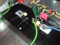
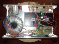
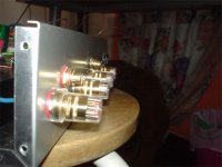
200VA 18-0-18 toroidal trannie used. Rectification by ON Semi MUR860. Binding posts are all WBT clones. Heatsink is oversized for this application... Hardly gets warmed up.
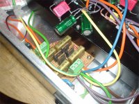
On with the pictures...
(Ignore the Earth wire around the binding posts... it's there to add 'thickness' so that the binding posts can be mounted properly)
Right channel done... Left channel half done...
Resistors:
Zobel uses 5W Dale 1% NS-5.
Carbon 5% used between ground and earth, and for LED.
Everything else 1% metal films.
Capacitors:
4.7uF Blackgate-N for input dc blocking.
Wima 0.22uF MKP for zobel.
Nichicon Muse 1000uF per rail per chip for PS filtering.
1uF MKS used across both rails, soldered directly onto chip.
0.1uF used between ground and earth.
0.1uF Rifa X2 used as snubber caps.
200VA 18-0-18 toroidal trannie used. Rectification by ON Semi MUR860. Binding posts are all WBT clones.
Heatsink is oversized for this application... Hardly gets warmed up. On with the pictures...
(Ignore the Earth wire around the binding posts... it's there to add 'thickness' so that the binding posts can be mounted properly)
Right channel done... Left channel half done...
Attachments
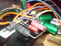

That's great, your soldering work looks as messy as mine (and do I recognize Sim Lim prototyping boards?).
Not to worry too much, the electrons don't care. But do check out safety, sometimes without the "anchor" of a board, and with thick connecting wires, things can get bent into a short, with those tight spaces. I have made this kind of mistake several times...
Have fun and enjoy,
(and do I recognize Sim Lim prototyping boards?). Not to worry too much, the electrons don't care. But do check out safety, sometimes without the "anchor" of a board, and with thick connecting wires, things can get bent into a short, with those tight spaces. I have made this kind of mistake several times...
Have fun and enjoy,
Hi there - how does the amp sound, and what speakers are you using with it?
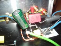
I also noticed that in post #3, the top of one of your supply caps looks VERY close to touching the tab of one of the rectifirer diodes. I'd look at that if I were you.
(I think the metal casing of most el. caps is connected on of the terminals..)
I also noticed that in post #3, the top of one of your supply caps looks VERY close to touching the tab of one of the rectifirer diodes. I'd look at that if I were you.
(I think the metal casing of most el. caps is connected on of the terminals..)
MBK said:That's great, your soldering work looks as messy as mine
Not to worry too much, the electrons don't care. But do check out safety, sometimes without the "anchor" of a board, and with thick connecting wires, things can get bent into a short, with those tight spaces. I have made this kind of mistake several times...
Have fun and enjoy,
Haha! The wires actually appears to be more rigid... my excessive tinning seems to have tinned the inside of the insulation.
BlackDog said:Hi there - how does the amp sound, and what speakers are you using with it?
I also noticed that in post #3, the top of one of your supply caps looks VERY close to touching the tab of one of the rectifirer diodes. I'd look at that if I were you.
(I think the metal casing of most el. caps is connected on of the terminals..)
The sound is great! Don't really know how to describe its sound. Perhaps I should say they sound rather 'balanced'. I'm using them with KEF Cresta 1 speakers.
As for the supply caps, that's just the camera angle. It's actually a fair distance from the rectifiers.
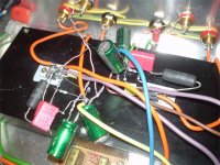
Nuuk said:You may find it easier to use solid core wire rather than the stranded. It makes for easier soldering in tight spaces and (IMHO) sounds better.
Other than that, a good job.
Thank you!
As mentioned above, the stranded are actually quite rigid after my excessive tinning.
Solid cores can let me have a neater layout, but they are far too difficult to bend under such tight spaces. Might try them out in the future. Solid cores can let me have a neater layout, but they are far too difficult to bend under such tight spaces.
No really if you use 0.6mm and I have even hardwired a Gainclone with 1.0mm!
skyraider said:Just curious, with such a big transformer why didnt you go for higher power opamp like 3875/3886?
Or is it that you just prefer 1875?
Have tied many times with the 3875/3886, but always end up with massive DC offset...
So I did up the 1875, til my planned tube amp can be realised...
>>>Have tied many times with the 3875/3886, but always end up with massive DC offset...
I would try to tackle that DC problem first, if I were you.. 3886 is much better sound. But if you are happy with 1875, no problem. End of this issue.
Did you try using different resistor for the zobel?
I would try to tackle that DC problem first, if I were you.. 3886 is much better sound. But if you are happy with 1875, no problem. End of this issue.
Did you try using different resistor for the zobel?
skyraider said:>>>Have tied many times with the 3875/3886, but always end up with massive DC offset...
I would try to tackle that DC problem first, if I were you.. 3886 is much better sound. But if you are happy with 1875, no problem. End of this issue.
Did you try using different resistor for the zobel?
Hehe...
This project was built with spare components entirely, so I'll just leave the zobel as it is.
mod_evil said:Ohhh... very good constrution... simple and easy...
Please post the schematic... do you use the datasheet schematic or you construction one schematic?
Thanks for attetion.
Thank you!
The schematic is basically derived from the datasheet, with some values changed, components added/omitted.
With regards to this schematic (http://202.186.86.35/audio/articles/2002/1/3/audiofile/diyden2.gif), R1 was changed to 47k as I had these resistors on hand. A 4.7uF BG cap was used between the RCA (J1) and R1 to block DC. C1 was omitted and R4 changed to 18k. I don't really require the high gain, so I slightly lowered it.
Cheers!
- Status
- This old topic is closed. If you want to reopen this topic, contact a moderator using the "Report Post" button.
- Home
- Amplifiers
- Chip Amps
- My LM1875 gainclone... point2point...