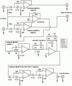
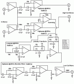
I currently have my sub crossed at 100Hz, and I have a linkwitz transform. I feel that it is time to create proper preamp with high pass filters. Basically, is my current circuit ok, or should I add some unity gain buffers anywhere? I calculated the values for the filters using the SLOA093 document from Texas Instroments. I have built each filter seperately on breadboards, and they work ok. I just dont know if I can stick them together like I have.
Attachments
all filters show are 2nd order, likely making them 12dB/oct unless they are signifigantly overdamped which i'm betting against given the closeness of values.
note that the source impedance is not shown. you may acheive better results adding a buffer on the inputs.
have not checked the values but it is likely the rumble filter and linkwitz transform filter will be near the same frequencies.
note that the source impedance is not shown. you may acheive better results adding a buffer on the inputs.
have not checked the values but it is likely the rumble filter and linkwitz transform filter will be near the same frequencies.
Yeah, a buffer at the front end would be a good idea because there are a few stages to drive and you can never be sure what the source impedance is. A buffer on the low out mono is also needed as mentioned for the pot.
I would also add a resistor of 22-100 ohms at the output of each op-amp that will drive a cable to swamp against capable capacitance possibly sending the op-amp into instability.
You might also like to simply parallel two 0.1uF for your sub low-pass as well instead of using a 0.22uF, but this is being a little picky and I guess you are short on space. I'd also look into cascading two of those filters to cut off more sharply.
Evan Shultz said:You need a buffer at the very end to prevent the pot from getting loaded down.
Why not place the pot before the rumble filter instead?
No additional buffer needed.
richie00boy said:I would also add a resistor of 22-100 ohms at the output of each op-amp that will drive a cable to swamp against capable capacitance possibly sending the op-amp into instability.
The buffers, or all the opamps?
You might also like to simply parallel two 0.1uF for your sub low-pass as well instead of using a 0.22uF, but this is being a little picky and I guess you are short on space. I'd also look into cascading two of those filters to cut off more sharply.
Which filters? The lowpass?
Matttcattt said:The buffers, or all the opamps?
richie00boy said:output of each op-amp that will drive a cable
So that would be the buffers then.
Matttcattt said:Which filters? The lowpass?
richie00boy said:for your sub low-pass as well instead of using a 0.22uF
It would seem so.
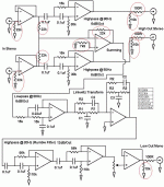
Matttcattt said:I've updated the diagram to check i've got the right idea.
For the summing op-amp I would use lower value resistors (like 22k).
You have an input buffer now.
Also, you will optimize dc-offset if instead of connecting NI directly to ground you use a resistor.
That resistor value should be the parallel combination of the other three resistors.
richie00boy said:Looks good but those 10k resistors on the output to ground are redundant.
No, they are not redundant.

The chips need a path to ground when there's nothing connected on their outputs.
richie00boy said:Why is that Carlos? In the dozens of such circuits I have built it has yet to appear a problem. Sure the input if floating needs them to provide bias current, but I don't see why the output needs them.
The output should not be floating, as it will if there's no device connected.
It needs a return path.
Just try what happens when an op-amp has it's output(s) floating. Touch the op-amp with your finger and feel the heat.
- Status
- This old topic is closed. If you want to reopen this topic, contact a moderator using the "Report Post" button.
- Home
- Amplifiers
- Chip Amps
- Active Filter Network


