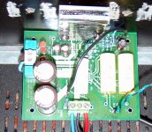
Finally got around to testing this amplifier -- THD + N averages 0.01% across the audio spectrum -- the 3dB down point is about 10Hz -- the longest sinewave test I did was 3 hours at 120 watts into an 8ohm resistive load -- and it didn't blow up! As I have said before, the device must be firmly affixed to the heat sink -- and I am using a 12V fan to cool it -- the fan runs at 7V which is quieter than the hard-drive on the TIVO:
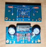
it's a proto -- the big polypropylene caps have been moved for the boards that were sent out.
An externally hosted image should be here but it was not working when we last tested it.
it's a proto -- the big polypropylene caps have been moved for the boards that were sent out.
output graphs -- into a resistive load:
An externally hosted image should be here but it was not working when we last tested it.
Banned
Joined 2002
diysmartdeep21 said:what are the ratings of your transformer?
Im planning to use toroidal transformer with the LM4780 ic and tell me what is the capacitor value that you are using per rail...
in the bridged configuration one half of the LM4780 is inverting, the other is non-inverting -- the difficulty with the bridged configuration is that the power dissipation of the chip as heat
(not sound) is much greater than a "non-bridged" -- National Semi says it is 4 times as much, I actually measured it as being somewhat greater !
my transformer is 400VA -- I think that this is about right for two bridged devices (if you are using it to drive music through speakers), if you were using it as a laboratory amplifier I would probably go to 600VA.
Distortion is comparable to that outlined in the Nat Semi website for a single, non-inverting amplifier (edit) (note that I cut out of the graph the 78kHz and 100kHz distortion from the graph, it is 7.4% at 78kHz and I shut it down before going to 100kHz):
An externally hosted image should be here but it was not working when we last tested it.
Please help with noise... A 120 Watt Bridged
I have this bridged LM4780, built & double checked the bom, but have some problems:
When music somes on low, it sounds ok. As soon as I turn up the volume a tad, I hear "scratching", and somthing similar to white noise starts adding more and more to the music. This noise stays there when turning off signal. But dissapears when muting on/off. And it is silent until it gets a signal above a few mV again...
I tried adding 22pF caps over the ~46.4-51.1k feedback resistors, and 22pF on input.
No change. ( PSU gives +/-36V DC, and heatsinks are big...)
What next?
Arne K
Last edited:
I hear "scratching"
That sounds like the SPiKe system trying to protect the IC. You will have to doublecheck your amp for shorts, broken leads, correct component values and orientation, correct voltages everywhere, etc. Since the schematic is an exact copy of the datasheet application, it should work when correctly built.
I also guessed it is some SPiKe issue...but why? Oscillation?
I have checked all component values. And all soldering-flux cleaned. Voltages...? I checked the mute-voltage, found it somewhat low to the mute-pins, tried a more direct route thru a 4,7k resistor, it is still low at ~-4,xV
Arne K
I have checked all component values. And all soldering-flux cleaned. Voltages...? I checked the mute-voltage, found it somewhat low to the mute-pins, tried a more direct route thru a 4,7k resistor, it is still low at ~-4,xV
Arne K
Attachments
The mute pin requires current. Testing voltage does not answer the wrong question.I checked the mute-voltage, found it somewhat low to the mute-pins, tried a more direct route thru a 4,7k resistor, it is still low at ~-4,xV
Using voltage drop and resistor value you can calculate the mute pin current, then check against the datasheet. Are there two mute pins?
Hi Red,
4k7 seems very low for mute pin resistor using +-36Vdc supply.
National state the chip needs <0.2mA to turn fully on.
Any resistor value between 24k and 68k will satisfy this current requirement.
They also state that the amp starts to turn off when mute current ~<=0.15mA.
Your 4k7 will start to turn off when the supply voltage is down to 4V+ 4k7*0.15mA i.e. ~ 4.7Vdc.
The 9V lower limit has already shut down the power amp. The mute comes in far too late on loss of power.
Cobra2 make sure the LM4780's are mounted on the heatsink properly and that you are using insulating pads between the chips and the heatsinks. Also make sure all of the power wires +V, -V-, GND are connected properly. Also I would recommend keeping all of the wires short as possible and keeping the high current wires (such as power wires and speaker wires) away from the small signal wires and components as much as you can. Return all grounds to a single point seperately i.e. use star grounding scheme.
- Status
- This old topic is closed. If you want to reopen this topic, contact a moderator using the "Report Post" button.
- Home
- Amplifiers
- Chip Amps
- Bridged LM4780 Amp