If I use a split supply lm1875 circuits, what parts can be removed from national's schematic?
I don't see the necessity of the following components, I'd like some input on their purpose and if they are necessary:
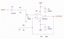
R1, R2 and C1 seem to filter the input, could R1 and R2 be replaced with a potentiometer and C1 removed completely? I assume this will allow more DC on the input though.
C2, C3, and C4 can be removed completely?
Is the zobel on the ground side of the speaker necessary?
I am trying to minimize parts, as I'd rather wire the thing p2p.
Thanks for the input, I want to learn while I do this.
-Adam
I don't see the necessity of the following components, I'd like some input on their purpose and if they are necessary:
R1, R2 and C1 seem to filter the input, could R1 and R2 be replaced with a potentiometer and C1 removed completely? I assume this will allow more DC on the input though.
C2, C3, and C4 can be removed completely?
Is the zobel on the ground side of the speaker necessary?
I am trying to minimize parts, as I'd rather wire the thing p2p.
Thanks for the input, I want to learn while I do this.
-Adam
If you want the absolute minimum in external components you can use this chip with 3 resistors and a pair of capacitors. Use the reistors In- to out (20k), In- to ground (1k), and one from In+ to ground (100K) the last resistor can vary in value depending on if you decide to use a pot in front of it or not. As for the filter caps 470uF seems to work well with this chip, some favour 1000uF. I also typically place a 1K resistor in series with the input, and use a 0.47uF cap to block any DC, but these are entirely optional.
And yes the minimal configuration will sound VERY good.
Basically you are rebuilding the gaincard")
Best of luck.
G.
And yes the minimal configuration will sound VERY good.
Basically you are rebuilding the gaincard
Best of luck.
G.
Thats not quite what I was talking about...but it would work. Change the pot to a 100k resistor. If you want to use a pot put it before the input cap, you can also do away with the 1k resistor in this case (but you might as well leave it in). Connect the wiper of the pot to the input cap, one side will be connected to the input signal, and the other to ground. Also I would recomend a 10K pot with a 100K resistor to ground, if you are using a 100k pot then use 1Mohm to ground. Really what you are building here is the most basic of non inverting opamps.
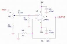
Your P1-R2 series is wrong, the second schematic here is a basic non-inverting gainclone, shows 3875 but exactly the same is OK for 1875.
I'd suggest low-ESR caps (eg Panasonic FC) on the power rails next to the chip when not using the 100n films C3 & C4, and maybe leaving an option on the pcb to use or link out C2.
The linked page gives the Gainclone philosophy so you'll be able to make your own mind up.
I'd suggest low-ESR caps (eg Panasonic FC) on the power rails next to the chip when not using the 100n films C3 & C4, and maybe leaving an option on the pcb to use or link out C2.
The linked page gives the Gainclone philosophy so you'll be able to make your own mind up.
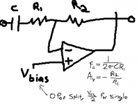
if you really want a simple circuit, you can build the inverting version.
this amplifier has an input cap, 2 feedback resistors. then the chip.
this is the minimum _required_. but its a good idea to add the local capacitors and the 0.1uF ceramics. this may not be required. the zobel you can add as well. and you might concider putting a bias resistor on the non-inverting terminal.
please note that national has the inverting circuit misprinted in a few places. they sometimes place a resistor to ground, which lowers the input impedance.
edit -- adding a pic. i left out the speaker, zobels, and supply filtering. you might also put a resistance of R2 in series with the noninverting terminal.
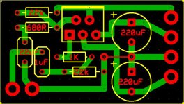
Attachments
Has any of these been built?
Is the circuit design for the Copper Amp by Mick Feuerbacher compatible with the LM1875?
Is the circuit design for the Copper Amp by Mick Feuerbacher compatible with the LM1875?
.........edit -- adding a pic. i left out the speaker, zobels, and supply filtering. you might also put a resistance of R2 in series with the noninverting terminal.
I hope not. The poster has added an edit stating that the necessary components have been omitted from the posted schematic.Has any of these been built?
I count 9 components missing, that's more than shown in the simplified schematic.

For DC coupled design, the input load must be directly at 10k to 11k, so either remove that 100k or set it parallel (not series) to the potentiometer.
Install a 4.7uF//10nF capacitor in series with signal+, between potentiometer and RCA jack. You now have technically a "mixed coupled" design.
The gain is insufficient for modern use with computer and mp3 player.
Change RI (feedback-shunt) to 820R. Change RF (feedback resistor) to 27k.
Change the 1k stopper resistor to 470R, if you like.
The non-specific 2200uF caps will be a cause of bad performance. Instead. . .
For this type of design, go with Audiosector's ideas on 1500uF Panasonic FC. Specify either "Low Impedance" or "Low ESR" directly printed on your schematic.
P.S.
The DC/Mixed coupled Gainclone amplifier will not have as good of dynamics, as long a life, or as much speaker safety as a fully equipped and properly AC coupled amplifier. See the Wikipedia on the practice of Muntzing to see that while omitting parts might make something simple and inexpensive, it also decreases performance, in most cases.
- Status
- This old topic is closed. If you want to reopen this topic, contact a moderator using the "Report Post" button.
- Home
- Amplifiers
- Chip Amps
- More LM1875 questions(minimized circuit?)