Hi everyone, I was just curious how low a voltage I can run an LM1875 on. I am not looking for ear splitting volume levels, as this will be for an office system. Although I have more suitable transformers sitting around what I would really like to use is an 8-0-8 center tapped unit that I pulled from an old UPS. It looks like it will deliver plenty of current so that will not be an issue, but with such low voltage should I beef up the capacitance from 1000uf per chip per rail to say 2200 or so?
Thanks!
Thanks!
Gcollier said:Hi everyone, I was just curious how low a voltage I can run an LM1875 on. I am not looking for ear splitting volume levels, as this will be for an office system. Although I have more suitable transformers sitting around what I would really like to use is an 8-0-8 center tapped unit that I pulled from an old UPS. It looks like it will deliver plenty of current so that will not be an issue, but with such low voltage should I beef up the capacitance from 1000uf per chip per rail to say 2200 or so?
Thanks!
The datasheet says that it needs at least 16vdc to run (from V+ to V-), so it appears like your transformer will work, providing approximately +/- 11v unloaded. (22vdc total) You could try using 1000uF first per rail. Don't set your gain to high, or you will have clipping.
--
Brian
Re: Re: LM1875...how low can you go?
Ah ha...that must be what I was experiencing...I was running with a gain of 20 and it worked just fine at low volume levels but when I turned it up....lets just say no good. Anyway I'll try reducing the gain. It honestly never occured to me to that the amp was clipping
Thanks Brian
BrianGT said:
...Don't set your gain to high, or you will have clipping.
--
Brian
Ah ha...that must be what I was experiencing...I was running with a gain of 20 and it worked just fine at low volume levels but when I turned it up....lets just say no good. Anyway I'll try reducing the gain. It honestly never occured to me to that the amp was clipping
Thanks Brian
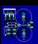
Here is the PCB I plan to use
Here is an image of the PCB I plan to use. It is a very small, single sided. Right now everyting is P2P. If anyone has any comments or suggestions please feel free. My goal here was to go relatively small. Obviously I could use a regulated supply and put smaller supply caps on the PCB, but my transformer doesn't likely have enough "overhead" voltage for regulation. And yes I could put a cap on the input but all my LM3875 gainclones are working just fine without.
Thanks
Almost forgot, the feedback resistor could be soldered directly to the pins, or under the board...I have also put it under the bend in the pins before without a problem.
Attachments
Since the transformer has current, you could fore go using the center tap and wire it so you get plus or minus 22 volts (16 V AC). Simplest is with 2 half wave rectifiers, but needs bigger caps because of half wave operation. Or two full wave bridges. YMMV. Or you could bridge the amps if you decide you need more sound. But, your original plan seems fine. 
If anybody is wondering, sregor is referring to a (half-wave) voltage doubler. +/-11V would give about 5W; +/-22V about 20W (from datasheet). Capacitance is cheap, I think a doubler is a good suggestion.Since the transformer has current, you could fore go using the center tap and wire it so you get plus or minus 22 volts (16 V AC). Simplest is with 2 half wave rectifiers, but needs bigger caps because of half wave operation. Or two full wave bridges. YMMV. Or you could bridge the amps if you decide you need more sound. But, your original plan seems fine.
- Status
- This old topic is closed. If you want to reopen this topic, contact a moderator using the "Report Post" button.
- Home
- Amplifiers
- Chip Amps
- LM1875...how low can you go?