How dangerous is it to have too high a voltage feeding the LM4780. A toroid I'm looking at to power a stereo 6 channel (tri-amped), 6 chip paralleled GC is has an unloaded voltage of 31.6V. According to my little windows calculator, that's 43.5VDC, higher than the chip is rated for.
Would the extra volt and a half over the rating cause issues? According to the specs, with the secondaries in parallel, the output is 29V @ 20A. 38.8VDC after rectification. I wouldn't mind avoiding the complication of a regulated PSU, but the other option would be to regulate it down to 36V or so.
I definitely want to avoid spike visiting me, has anyone tried this? If so, what were your results?
IIRC the LM chips can tolerate higher voltages with higher impedance loads and with NO signal applied. If you have several chips you can experiment... if the first one pops, install another with a regulated supply or unwind a few volts off the transformer's secondaries if possible. Perhaps a little resistive load of the power supply would lower the voltage enough to be tolerable. Perhaps the quiescent current of your circuits combined would be enough.
The safest route of course is to look at ANOTHER transformer.
I am pretty sure this has been discussed before...be creative with your search parameters.
The safest route of course is to look at ANOTHER transformer.
I am pretty sure this has been discussed before...be creative with your search parameters.
figure the PDMax and delta-T and heat sink appropriately -- you can get a lot out of these chips if you keep them cool (hint -- try a fan!). if you dont heat sink adequately you will wind up with power output well below what you anticipate since the SPIKE will kick in.
SPIKE isn't a bad thing, it sure beats soldering these babies!
SPIKE isn't a bad thing, it sure beats soldering these babies!
Well, I decided to go with a dual secondary 600VA 27V unit. That'll be within the rating of the chip, even unloaded.
My PS will be a 600VA 27-0-27
2 35A bridge rectifiers
4 68,000 50V 105C Nippon large can filter caps (2 per rail)
10uF and 100nF on the amp board.
The amp will have 6 seperate boards with 6 chips, one per channel (each 4780 is paralleled).
A question about grounding though. Most people suggest a star ground where everything's returned to the same point, usually at the caps 0V point.
I'd planned to run 12 guage wire to each amp board from the cap common, and then have the line input, speaker output and feedback grounds on each board go to that 0V input. Should that work as well?
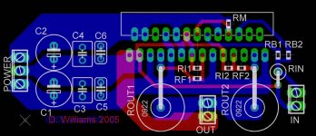
Here's the amp board. It's fairly wide at about 2 1/2 inches, but slightly less than an inch deep. I left the extra area between the caps and the chip to make sure it was easy to screw the retaining bar into place.
Rm is 8.2k
Rb's are 1k 0.1%
Ri's are 1k 0.1%
Rf's are 20k 0.1%
Rin is 47k 1%
Rout's are 5W 0.1Ohm
C1 & C2 are 10uF
C3 & C4 are 100nF
C5 & C6 are 1nF
What say you all? Does the grounding scheme look good? are the traces thick enough?
Rm is 8.2k
Rb's are 1k 0.1%
Ri's are 1k 0.1%
Rf's are 20k 0.1%
Rin is 47k 1%
Rout's are 5W 0.1Ohm
C1 & C2 are 10uF
C3 & C4 are 100nF
C5 & C6 are 1nF
What say you all? Does the grounding scheme look good? are the traces thick enough?
Attachments
thomas997 wrote:
Yes 3 power diodes each per rail. will drop 2...3volts/rail.
No schottky or FR diodes...
Good idea!!You can also try adding some extra diodes to drop the voltage.
Yes 3 power diodes each per rail. will drop 2...3volts/rail.
No schottky or FR diodes...
What say you all? Does the grounding scheme look good?
Yes and no. The feedback ground should not pass through the filter capacitor tie-point on the way back to the center tap input. You will get hum this way. Not just a little bit, either.
You already have a top-layer trace running to pin 3 of the 4780; disconnect it there and run it back to the POWER connector. If you have the time, I suggest making two runs for a HQG, one for the input signal and one for the feedback resistors. Since those caps are relatively small, and the charging currents will likewise be small, the speaker ground is fine where it is.
RMute is going to dissipate about 0.25W -- make sure you size it correctly.
If you are going to use surface mount, then the 100nF caps could be SMT also. Mount these as close to the power pins of the LM4780 as possible.
you might also want to check the diameter of the pads and drill setting for the LM4780's pins -- these are 21mils wide, so a standard DIP pad opening (drill diameter) is going to be too wide. Set the drill for these at 25mils.
jackinnj said:RMute is going to dissipate about 0.25W -- make sure you size it correctly.
If you are going to use surface mount, then the 100nF caps could be SMT also. Mount these as close to the power pins of the LM4780 as possible.
you might also want to check the diameter of the pads and drill setting for the LM4780's pins -- these are 21mils wide, so a standard DIP pad opening (drill diameter) is going to be too wide. Set the drill for these at 25mils.
Good point. The drill setting appears to be 32 mils, I used the LM&OPA library that was posted up (I believe) on CadSoft's website. About Rmute, after looking at the graphs on the datasheet it seems that even 0.3mA should be enough for each mute pin. If I pull 1mA from the two together, that's about 32.5kOhm. I'll switch Rm to a 27kohm resistor 1/8W, that's about 44mW of dissipation.
EnvisionAudio said:
Yes and no. The feedback ground should not pass through the filter capacitor tie-point on the way back to the center tap input. You will get hum this way. Not just a little bit, either.
You already have a top-layer trace running to pin 3 of the 4780; disconnect it there and run it back to the POWER connector. If you have the time, I suggest making two runs for a HQG, one for the input signal and one for the feedback resistors. Since those caps are relatively small, and the charging currents will likewise be small, the speaker ground is fine where it is.
Thanks for the tip, Envision. I've modified it a little bit, switching the 0603 Rm for a 0805, and C3-C6 are now SMT ceramics, 100nF and 1nF. Does the grounding look better now?
Attachments
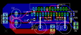
Does the grounding look better now?
You got it!
I just know this from experience. I made 50 PCBs with the feedback inadvertantly passing straight through the filter caps.
Needless to say, it constantly hummed. Of course, I didn't make that mistake on the prototype PCB. Lesson learned.Mr Teal said:
If I pull 1mA from the two together, that's about 32.5kOhm. I'll switch Rm to a 27kohm resistor 1/8W, that's about 44mW of dissipation.
oops, i put in one too few zero's in the calculator -- you're right. 1mA will do quite nicely.
demogorgon said:just wondering if anyone could tell me what the effects of using a larger than reccommended transformer is?
does spike refuse the chip to work, or is the +-96v just a number put inn to guarantie that the chip will work?
here's the equation --
PDmax = (|vcc|^2)/(2*RL* pi^2) --
Vcc is the absolute value of the rail potentials -- the higher this, the more power the chip dissipates as heat. it gets worse if you use the bridged configuration -- PDMax must be multiplied by 4!
well i want to use just one chip of LM 4780 and what must be the voltage ratings and the power ratings of the transformer toroidal ......
like i want to use 35-0-35 with how many amperes of current for the transformer?
please give me some number ive asked many times i didnt get it in the datasheet please tell me.... just one number what does it makes any difference...
please guys....
like i want to use 35-0-35 with how many amperes of current for the transformer?
please give me some number ive asked many times i didnt get it in the datasheet please tell me.... just one number what does it makes any difference...
please guys....
pinkmouse said:250VA.
The bridged LM4780 drew 2.5 amps on a 120 VAC Line when maxing out at 120 Watts -- a good chunk of the energy goes to keep the laboratory warm via the heat sink and fan, but about 10 VA goes into transformer inefficiencies, maybe 10+ watts get burned up by the IR loss in the rectifiers. All the rest goes to make sine waves.
What I have read seems to indicate that you don't have to size the transformer for sine-wave testing -- there is some validity to sizing for the envelope of music you are going to play and this can be a lot less -- but you have to also take into consideration the dissipation of the chip and the other attendant losses cited above.
- Status
- This old topic is closed. If you want to reopen this topic, contact a moderator using the "Report Post" button.
- Home
- Amplifiers
- Chip Amps
- Overvoltage to LM4780