It's a good design rule to have them in cases where it takes a rather long time to discharge the caps but... also if youi have 78xx regulators and possibly microcontrollers. Under a certain voltage the current consumption of these regulators is _very_ small and therefore the discharge time very long. Some microcontrollers (Microchip) may not be 100% reset if the voltage not goes under 0.6 volts or so. I'll guess this is not a big problem in audio but you may get unpredictable results if the voltages are equally discharged.indoubt said:How important is the bleeder resistor?
Can it be ommitted or is it essential?
(I was called in a case where there were emergency power checks with rather short power interruptions and the design did latch up due to 99% reset.)
Hi,
When i use Carlos' Snubber PSU, and i use different main capacitors, for example 22.000 instead of 10.000µF, are the other parts have to be recalculated?
And has anyone ever compared the sound of the regulated snubber PSU to the unregulated snubber PSU?
Wich one sounds better/more natural?
regards,
Stephan
Oh! Very useful thread! I am designing my own ausio-amp PSU at the moment.
Though I still question if the effect, re sound quality, will be real or psychological. Until someone does some double-blind testing we'll never know: opinions without scientific rigour are less than valueless because they lend credence to fiction and an active imagination (which we all have).
Though I still question if the effect, re sound quality, will be real or psychological. Until someone does some double-blind testing we'll never know: opinions without scientific rigour are less than valueless because they lend credence to fiction and an active imagination (which we all have).
LOL Thorsten, you made my day! So you are actually saying that 1000uF caps are better than 10000uF caps with 100nF bypass caps? And what about the bass response? I bet it will suck if you use 1000uF caps, even if they are low ESL....
Perversly, using a low impedance, low ESL 1,000uF Cap as in the gaincard and many gainclones approaches this much closer than a big 10,000uF PSU Capacitor with added bypassing in most cases.
Sayonara
Really, you are the one that should not be making amplifiers. What engineering principle supports your theory? I saw one of your inverting GC (you called it Gizmo) and it is excruciatingly ridiculous! Instead of using a Ci like the NatSemi suggests, you use an input coupling capacitor directly into the signal path.
To the rest of the guys here, if you have doubts, read this excellent review on Thorsten's little creation.
LM3875
I might disagree in a point or two. Completely discharged caps will take a bigger inrush current. Plus, capacitors shouldn't be discharged completely because that will shorten their lives. Bleeding resistors are useful in standalone power supplies, where it is critical to discharge those caps. In audio amplifiers, it will worsen the overall power consumption and efficiency.Discharging the caps at power off is a good thing, as it also preserves their life.
And, important too, the amps shuts down quicker after power-off.
Last edited:
well mr cumesoftware,
are you really sure you know what you are talking about ?
I read lots of words but I don't notice much real understanding.
just to balance this discussion . . . for me, some of your suggestions look like a recipe for horrible sounding amps.
I wonder if you speak from real personal experience or just quoting other peoples theories.
Last edited:
I really speak from my personal experience. I build amps, you know! And anyone should agree that using Ci as suggested in the NS datasheet is better that Thorsten's alternative to use a capacitor right at the input. I try to avoid coupling caps, unless there is no alternative. Ci as NS datasheet suggests is not placed directly in the signal path, and that makes a huge difference. The design he used resembles a cheap amplifier. I'm sure the bass will distort a lot! And yes, I have built a LM3875 amplifier based on the datasheet and it works. It has four beefy 10000uF capacitors and still lacks some low bass response (concluded that by hearing "Bass, I Love You" at high levels with 4 ohm speakers). Otherwise it is excellent! I wouldn't try to reinvent the wheel because NS engineers are quite competent and they know better than anyone how to use the LM3875 they designed. And no way I would use Thorsten design. No wonder that many LM3875 end up burning. Inverting amplifiers and a lousy point-to-point construction with a chip. Ridiculous!well mr cumesoftware,
are you really sure you know what you are talking about ?
I read lots of words but I don't notice much real understanding.
just to balance this discussion . . . for me, some of your suggestions look like a recipe for horrible sounding amps.
I wonder if you speak from real personal experience or just quoting other peoples theories.
Really, Gaincard is crap, and so is Gizmo.
Probably the one of using a certain capacitor as intended. His demeanour doesn't worry me a bit.Mike, be specific, which suggestion do you think is a "recipe for..."
Last edited:
cumesoftware
The DC coupling cap at the input and the NFB DC blocking cap Ci serve 2 different functions.
The input cap is there to block any DC offset present on the signal from the source. If it is not used, any DC offset present in the source will be multiplied by the gain of the amp with disastrous results for your woofer cones.
Ci is there to roll off the gain of the amp at DC to unity so that the DC offset generated by the amp itself does not get amplified by the gain of the amp. As long as that offset is small (<50-100 mV say) Ci can be safely eliminated.
The main reason why the DC blocking cap has a bad reputation is that it forms a high pass filter with the resistor to ground which defines the input impedance of the amp. The rolloff point of this filter is usually set too high, resulting in audible phase effects in the lower bass. With a -3dB filter rolloff point of 1.5 Hz or less and a good quality polypropylene cap in this position, the input DC blocking cap should be inaudible.
See also Andrew T's posts about the interaction of the RC Time Constants of the input filter, feedback network/Ci and power supply capacitance/speaker impedance and what the optimum relationship is between each.
Last edited:
So as Ci. When using Ci any DC offset at the input won't get amplified. That means that a 0.5V offset at the input will cause an 0.5V offset at the output. Without Ci, this offset would be multiplied by the gain. And that is because Ci has an infinite resistance to DC and thus the amplifier will have unitary gain for that DC component of the signal. It does not null the DC offset as well as the input cap, but it is equally good considering that these amps are set to have a gain around 20V/V or 30V/V. Normally, DC offset at the input is in the order of a few millivolts.cumesoftware
The DC coupling cap at the input and the NFB DC blocking cap Ci serve 2 different functions.
The input cap is there to block any DC offset present on the signal from the source. If it is not used, any DC offset present in the source will be multiplied by the gain of the amp with disastrous results for your woofer cones.
Not quite. Without Ci, it is easy to get 150mV or more at the output with the input connected to ground. You must take into account that the dual power supply used to feed the LM is not perfectly balanced. I personally came to that conclusion. With Ci, offset is as small as 15mV.Ci is there to roll off the gain of the amp at DC to unity so that the DC offset generated by the amp itself does not get amplified by the gain of the amp. As long as that offset is small (<50-100 mV say) Ci can be safely eliminated.
It is not because the rolloff point is set to high. Caps at the input can be small without any interference in terms of bass filtering. Usually the input resistance is very high. The problem is colouration added by those capacitors. I really try to avoid them because of that. On the other hand, Ci is placed marginally on the signal path.The main reason why the DC blocking cap has a bad reputation is that it forms a high pass filter with the resistor to ground which defines the input impedance of the amp. The rolloff point of this filter is usually set too high, resulting in audible phase effects in the lower bass. With a -3dB filter rolloff point of 1.5 Hz or less and a good quality polypropylene cap in this position, the input DC blocking cap should be inaudible.
P.S.: For input decoupling caps I have a rule of thumb (when I have to use them): for a frequency of 10Hz, Xc should be 20 times smaller than the input impedance. That should be more than enough to avoid rolloff at audio frequencies.
P.P.S.: The LM3875 is nothing more than an op-amp. So the rules apply there too.
Last edited:
The snubber is the resistor. The cap is just there to determine which frequencies the snubber resistor gets to see, so it doesn't dissipate too much power. So I think that the cap value would stay the same, since the frequencies involved would be the same.
Not sure about the resistor but don't see any reason to change its value.
Not sure about the resistor but don't see any reason to change its value.
So if I parallel 3 LM338 I don't get 3 times less the output impedance and I don't have to take this in to account when calculating the resistor/cap value?
The values of the cap/resistor are different in the unregulated and regulated supplies. Shouldn't it be the same values?
~
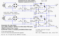
The schematics I'm using is the one on the pic.
thanks.
The values of the cap/resistor are different in the unregulated and regulated supplies. Shouldn't it be the same values?
~
The schematics I'm using is the one on the pic.
thanks.
Attachments
Last edited:
Yes, I know that.You can't just parallel 3 regs. You'd have to use ~0R1 balancing resistors on the output of each reg to prevent one reg hogging all the current.
What I don't know is how to change the parts in the snnuber to acomodate the new impedance of the 3 paralleled circuits.
I don't know that it's acting as a typical snubber, anyway. It looks more like a way to guarantee at least 0.47 Ohms of ESR for the 47 uF output cap, maybe since the cap's own ESR would drop quickly as frequency increased.
You could either use one snubber per regulator, or one snubber after their parallel outputs have been merged together, or, one per regulator and also one after the outputs have been merged.
If you want to know how snubber component values are calculated, there are several good papers on the web. Just google "snubber design".
If you have a scope and can put some fast-rising square waves into the amp that's being driven by the PSU, you might be able to use the practical method, at:
http://www.diyaudio.com/forums/powe...lm-caps-electrolytic-caps-30.html#post2828689
- Status
- This old topic is closed. If you want to reopen this topic, contact a moderator using the "Report Post" button.
- Home
- Amplifiers
- Chip Amps
- Carlos' snubberized Gainclone Power supply