What do you guys think?
http://www.electronet.dyndns.org/electronet/subamp/pictures.htm
I plan on giving this to my dad for christmas.
I know the speaker is trash, but it works pretty well, or at least much better than expected.
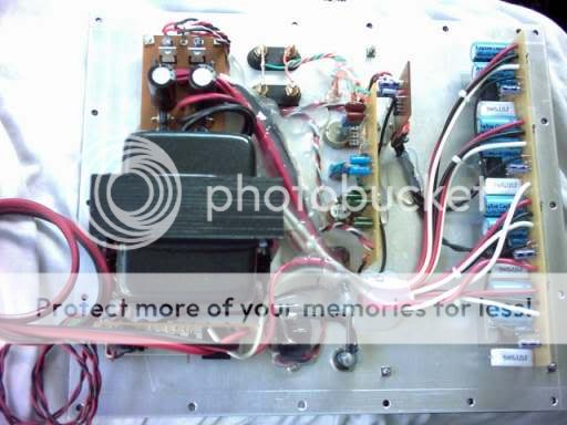
The amp is a bridged OPA549 design powered by a 175W transformer (I know, a little too small, but it's all I had). Page 2 shows pictues of the amp. It's built onto a piece of plexiglass.
Sorry if it's slow loading, because until I find a new website host, I have to host it myself. So, my server is an old 233mhz p1 pc, and my internet connection is a 1.5MB down/350k up DSL connection, so it's not the best for web hosting.
http://www.electronet.dyndns.org/electronet/subamp/pictures.htm
I plan on giving this to my dad for christmas.
I know the speaker is trash, but it works pretty well, or at least much better than expected.
The amp is a bridged OPA549 design powered by a 175W transformer (I know, a little too small, but it's all I had). Page 2 shows pictues of the amp. It's built onto a piece of plexiglass.
Sorry if it's slow loading, because until I find a new website host, I have to host it myself. So, my server is an old 233mhz p1 pc, and my internet connection is a 1.5MB down/350k up DSL connection, so it's not the best for web hosting.
opa54* sub amp Q?
would really like to see the layout you have, and component values. do you have a pcb file for this amp?
i am building a car gainclone for my midbass speakers, (parts express buyout 7inch in aperiodic enclosure)
i have a working smps that has 31 volt rails after rectification, and would like to regulate them down to 27-30v and add some caps to stiffen up the psu(car smps are week from what i have read)
im looking at lm-338 for regs, unless anybody thinks the lm-317 can be used for psu (only 1A but this is for midbass duty, with extra caps, and an already regulated smps it might work out with lm-317?)
pretty neat plexi cover to show your handy work !!!
Thanks for the comments.
I'll be posting this project on my website soon, so I'll also post the eagle files. When it's up, I'll let you know.
I guess I could decorate it more, but don't know if I will. You don't see it too much. I think the thing I want to do the most is add an LED light to it so the edges glow. OR, I was just thinking, I have a leftover set of 2 PC blacklights. All I'd have to do is build a 7912 regulator to run 12V into it. That would look pretty neat. But they could break with the rattling????
I forgot to mention, the box may be stained later on, but I am not sure when. Does anybody know where to get true black stain? I can't find it anywhere I look, and would prefer black stain over any other color. I may also add a nice grille to it.
Finally, those of you who looked at my pictures with a broadband connection, would you mind telling me how good the speed was? Hopefully it was acceptable!
Thanks again for all the comments,
Mike
soundNERD said:Nobody has any more comments?
I would really like to hear them!
May be it's of no consequence in this case, but noticed you attached the back cover with 4 corner screws.
If you really hammer it down (just over 40 - 50 W RMS), you will probably have serious venting air currents all along the borders or, if there is recessed bracing, noticeable rattling. Should like to hear from you.
Rodolfo
I actually have 10 screws, 3 across the top and bottom, and 4 down each side.
Plus, no air gets there because there is a board dividing the amp from the speaker and the wire going to the speaker is sealed so no air leaks with hot glue.
I was actually quite suprised when I first listened to it that there was absolutely no noticeable rattling unless you has your ear up to the amp. But either way, the speaker is much louder and you never notice it.
edit:
I misunderstood your post. You were talking about the back piece of wood. But the same reason applies. Either way, I think I'll add a couple more screws to it.
Looks good to me.. for some reason the pictures wouldnt load in firefox, but worked fine in IE.
What layout did you use for bridging, was it in the datasheet?
How does the power compare to a pair of 3886s?
Also what voltage are you getting out of the transformer?
oh and any hum at all, its kinda annoying when there is 60hz hum for a subwoofer :/
thanks
What layout did you use for bridging, was it in the datasheet?
How does the power compare to a pair of 3886s?
Also what voltage are you getting out of the transformer?
oh and any hum at all, its kinda annoying when there is 60hz hum for a subwoofer :/
thanks
I used the bridge schematic from AN-1192, but used 470k feedback resistors on each amp for enough gain to work with my reciever's output.
I have never heard a bridged 3886 amp, but I have never been impressed with any of national's chips in a subwoofer. The opposite goes for a full range speaker. national's chips are designed more for hi-fi audio, unlike TI's chips, which aren't really designed for audio at all.
But when comparing to commercial subs, I have noticed it performs better than them. This sub easily overpowers my infinity 600W 10 inch sub, and thats even a ported one. I have also compared it to a velodyne sub, with an 8" woofer and a 10" radiator, and found the velodyne to be a little too thuddy, while this seems to have much tighter, more controlled bass. To me, it sounds much better.
The power from the transformers is 36VCT 175W, but after the rectifiers, I never measured the voltage.
And, yes, there is a slight hum because I went for a standard transformer instead of a torrid and I think it's a little too close to the magnet of the speaker. But the hum is inaudible when sitting 10 ft away from it.
The only complaint I have with this is it does very well with running bass lines, but not so well with quick booms. Then, it gets a bit thuddy. I dobut it's the amp, but instead the speaker. I remember hearing this one in the store and it doing the same thing.
Other than that, I'm still suprised at how good something I made turned out. It's about time for me though!!
hm that seems like a fairly high voltage to be running the chips at.. maybe it drops a bit under load though? Datasheet says +/- 30V as "max".
So did you use the AN-1192 schematic straight, other than the change in feedback resistors?
You must have added the current limit and Ref voltage connection though right? I tied both of mine to ground and for some reason I cant get the amp to work..
Thanks
So did you use the AN-1192 schematic straight, other than the change in feedback resistors?
You must have added the current limit and Ref voltage connection though right? I tied both of mine to ground and for some reason I cant get the amp to work..
Thanks
Well, carlosfm and I were talking about these chips in a subwoofer a while back, and he said how his sub, using 2 opa549 in parallel running at a regulated +/-29VDC, which is 1V below the max, and they seem to run happily at that voltage.
I believe mine is running at about +/-25VDC, which is plenty enough below the max for them to run fine.
Yes, I used the exact schematic from AN-1192, and changed the feedback resistors as I said before.
I have also tied the ref to current limit, then connected them both to ground. Be sure the pcb connection is good (use a multimeter on resistance mode, touch to the main gnd trace and touch the other side to the ref and current pins). I spent about an hour trying to figure out why another amp I built using an OPA549 wouldn't play anything. The trace on the PCB had split (small enough to not be visible easily), and the chip was stuck in off mode.
Are you using a split or single supply?
Hi soundNERD,
It is really a very simple and effective way to use AN-1192 for bridging GCs, mine used a balanced line driver because all my GC modules were setup'd in a NI fashion. It really feels good to built something worth your time.")
BTW, here's a pic of what I built for a sub amp.
JojoD
It is really a very simple and effective way to use AN-1192 for bridging GCs, mine used a balanced line driver because all my GC modules were setup'd in a NI fashion. It really feels good to built something worth your time.
BTW, here's a pic of what I built for a sub amp.
JojoD
Very nice!
Did you build the metal plate yourself or recycle it from a subwoofer?
Looks like 4 chips? probably bridge / parallel? What chips did you use?
Have you connected it to a speaker yet? If so, how does it sound?
The only thing I may worry about that is the size of the heatsink. My amp uses only 2 chips, and the heatsink on it gets hot enough to hurt you if touched. 4 chips puts out twice the heat, and, from my view, the heatsink on your sub looks almost a little too small for how much it's cooling.
Other than that, very well done!
You can get pure black stain from www.rockler.com and look at the 'dry dyes' for black.
markp,
Thanks. I'm suprised I never saw it there before. I've looked at their store for it before.
I have tried black dyes in the past, and it pretty much ruined my speaker. The results were terrible. If I touched it I would get a bunch of black powder on my hands, so I had to clear coat it, making it glossy, which I ddin't want, to stop it. And the color was more of a dark gray than black.
But I found a black stain at rockler, next time I'm there I will look at it.
soundNERD said:Very nice!
Did you build the metal plate yourself or recycle it from a subwoofer?
Looks like 4 chips? probably bridge / parallel? What chips did you use?
Have you connected it to a speaker yet? If so, how does it sound?
The only thing I may worry about that is the size of the heatsink. My amp uses only 2 chips, and the heatsink on it gets hot enough to hurt you if touched. 4 chips puts out twice the heat, and, from my view, the heatsink on your sub looks almost a little too small for how much it's cooling.
Other than that, very well done!
Hi,
I built the plate myself, i mean cut, drill, sanding, etc.
Those are the same chips as the one you used and is trully in a bridge parallel config. It's already been working for weeks now, very good indeed.
I don't worry about the heat too much, when I build bridge parallel, I make sure that all the 4 separate amp sections have the lowest possible dc offset so that when connected in BP config, current will not conduct hence no extra dissipation.
Oh btw, I did subject the 549s in a torture test by clamping a 100W soldering iron on the heatsink just to test the thermal protection and it really works thereby protecting the chips.
The plate during painting....

- Status
- This old topic is closed. If you want to reopen this topic, contact a moderator using the "Report Post" button.
- Home
- Amplifiers
- Chip Amps
- My latest subwoofer - a bridge opa549 built onto a piece of plexiglass