I am designing a PCB based on carlosfm's thread in regards to Regulated PSUs.
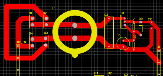
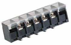
The attached screenshot is of half the board. The other half will be a mirror image. The intention here is to get feedback on my current design and how I can improve it before I go and do the other half.
This design is for DIY only, and I will not be making it commercially avalable, so now that we got that out of the way, please fellas, post your comments.
Thanks!
Attachments

Banned
Joined 2002
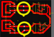
yeah well, my 10000uF rectifier capacitor measures 35mm diameter and 50mm height. Putting two of them on a PCB makes the PCB at least 70mm wide.
Digi01's boards are smaller due to the fact that he uses two boards where I would use one and also there are no PCB terminals. You solder everything onto the PCB.
The reason it is that big is mainly because I'm using premium components and all my caps are rated at 400V.
Digi01's boards are smaller due to the fact that he uses two boards where I would use one and also there are no PCB terminals. You solder everything onto the PCB.
The reason it is that big is mainly because I'm using premium components and all my caps are rated at 400V.
Banned
Joined 2002
D_GR8_1 said:yeah well, my 10000uF rectifier capacitor measures 35mm diameter and 50mm height. Putting two of them on a PCB makes the PCB at least 70mm wide.
Digi01's boards are smaller due to the fact that he uses two boards where I would use one and also there are no PCB terminals. You solder everything onto the PCB.
The reason it is that big is mainly because I'm using premium components and all my caps are rated at 400V.
Very true his do require 2 boards : O )
BUt im still looking for a regulator for 45V it's hard. but i'll continue : O )
Luke said:Hi D_GR8_1
how do I get stuff from Electus, do they do mail/web orders?
cheers arthur
Well first of all you need an ABN(Australian Business Number) or whatever the NZ equivalent is.
Then you go to their website
Electus
order your free catalogue and order away. I beleive that they have a store in NZ.
JasonL said:
BUt im still looking for a regulator for 45V it's hard. but i'll continue : O )
I am a little confused. Do you want to get 45V regulated out of the regulator? What are you putting into it?
If I understand right the regulators are rated base on the drop from input to output as opposed to the absolute output voltage.
Or are you trying to drop from say 45v in to 30v regulated?
Sorry JasonL, but I think we are going a bit out of topic here. 
The question I ask is for all you guys who are more experts that the rest of us mere mortals to comment on the design.
How can I improve it? Are the POWER/GND tracks the right place, the right size, and so on.
Also, Upopa, if I designed everything on 1 board, i.e PS/PA, arent I risking of introducing some noise into the amp?
- Status
- This old topic is closed. If you want to reopen this topic, contact a moderator using the "Report Post" button.
- Home
- Amplifiers
- Chip Amps
- Regulated PSU PCB