I'm going to build a 2-channel GC to compliment the speakers I am building this winter break. As you can tell by the impedance graph on John's site, the speakers are 4 ohm nominal, but dip to 3 ohms in several places along the freq range. I've read a number of places that it's a bad idea to drive anything less than 4 ohms with the National chips, so I figure i'll follow the spec found in their application note 1192 and build them using 2 LM3886's in parallel (per channel).
I haven't found too many documented gainclone projects using 2 chips in parallel per channel. Lots of them use the bridged/parallel configuration, but I think that's a little bit too complicated for my first amplifier project.
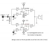
I modified the circuit diagram on Maarten's site (which looks like an exact copy of the non-inverting PA100 design from the National document) to include the input capacitor and resistor, and the voltage rails for the chips. It shows one channel... i've posted it below. The National spec suggested a voltage of +-37V for the PA100 design, so that is what I'm going with at the moment... so here are my questions:
Does the volume regulating pot go in between the audio in and ground?
Also, would there be any advantage in this case to build the inverting model (also found on Maarten's site) since it has the exact same component count as the non-inverting one?
I haven't done the math on the power consumption, but I'm assuming i'll be able to find a ~37V transformer capable of driving both channels? But I suppose there's no harm in using two if the design dictates it. I have about 5 weeks to build the GC and the speakers... hopefully it will be enough time.
I haven't found too many documented gainclone projects using 2 chips in parallel per channel. Lots of them use the bridged/parallel configuration, but I think that's a little bit too complicated for my first amplifier project.
I modified the circuit diagram on Maarten's site (which looks like an exact copy of the non-inverting PA100 design from the National document) to include the input capacitor and resistor, and the voltage rails for the chips. It shows one channel... i've posted it below. The National spec suggested a voltage of +-37V for the PA100 design, so that is what I'm going with at the moment... so here are my questions:
Does the volume regulating pot go in between the audio in and ground?
Also, would there be any advantage in this case to build the inverting model (also found on Maarten's site) since it has the exact same component count as the non-inverting one?
I haven't done the math on the power consumption, but I'm assuming i'll be able to find a ~37V transformer capable of driving both channels? But I suppose there's no harm in using two if the design dictates it. I have about 5 weeks to build the GC and the speakers... hopefully it will be enough time.
Attachments
Here is nice site (matches your request for 2xLM3886):
http://www.shine7.com/audio/pa100.htm
http://www.shine7.com/audio/pa100.htm
thanks savenger, that's the first time i've seen that site.Here is nice site (matches your request for 2xLM3886):
http://www.shine7.com/audio/pa100.htm
")
there are a couple of things about his schematic that deviate from the national spec and which i don't quite understand.
1) there is an extra resistor and capacitor between audio in and the rest of the circuit (R20 and C20).
2) there is a very tiny capacitor between + and - inputs on the LM3886s (220 pF). However, at any normal operating frequencies (20Hz - 20kHz) the capacitor will look like a giant resistance... so I wonder why it's there at all?
3) there is a 4.7 pF capacitor put in parallel with the feedback resistor.
4) there is a 2 ohm resistor and a 0.1 uF capacitor in series connecting the speaker output to ground (thus in parallel with the speaker the amp is driving).
My memory of my circuits course in college is a bit fuzzy... I'm having trouble figuring out why he added the components to the national design. Assuming the minimal-is-better approach to gainclone design, is there any reason the amp wouldn't work if I removed the modifications and stuck to the national spec? I can always add them later if I think there is a need. Now if they are necessary for the amp to function correctly (and they are simply missing from the an-1192 doc to make those schematics easier to understand), then that is another matter entirely.
PS - There is some additional modifications to the GND and Mute pins on the LM3886 and a few added capacitors connecting the rails to ground... Not sure what those are either. Perhaps that is a question for another day.

Datasheet example circuit also includes some of those extra components:
http://www.national.com/ds/LM/LM3886.pdf
Mostly these extra components prevent amp from oscillation.
1. Prevents high freguency entering in amp.
2. Prevents oscillation (i guess)
3. As above
4. Zobel http://www.trueaudio.com/st_zobel.htm
None of these components are mandatory if amp is stable and do not oscillate.
I may also be wrong , so i suggest you wait for another board member gives his impression.
http://www.national.com/ds/LM/LM3886.pdf
Mostly these extra components prevent amp from oscillation.
1. Prevents high freguency entering in amp.
2. Prevents oscillation (i guess)
3. As above
4. Zobel http://www.trueaudio.com/st_zobel.htm
None of these components are mandatory if amp is stable and do not oscillate.
I may also be wrong
, so i suggest you wait for another board member gives his impression.scone said:
there are a couple of things about his schematic that deviate from the national spec and which i don't quite understand.
All those components basically control bandwidth and filter what is not essential for audio.
Item 4 is a zobel and there was a specific thread over it. This should be implemented.
The other three are optional and should be tried and listened as to whether they improve or detract on what you listen or like to hear.
The feedback capacitors, C2 and C6, are also optional and should be used only if your amp has a large DC offset.
The chips used on the regulators (LT1083) are also expensive and hard to find. Use LM338 and do the supply Carlosfm suggests.
Carlos
I assume you are referring to the schematic found in this thread ? I've copied the schematic i'm talking about below so no one needs to hunt for itUse LM338 and do the supply Carlosfm suggests.

Also, I found an inconsistency in the 2x100W LM3886 GC schematics (http://www.shine7.com/audio/pa100.htm ). If you look closely, the values for C2/C6 and C5/C9 on the diagram are both shown as 100uF polarized caps. However, on the PCB layout, the board area for C2 and C6 is much bigger than the board area for C5 and C9. Also, on the pictures the C5/C9 caps look tiny compared to the C2/C9 pair. I assume that the value for C5 and C9 must be different than stated, but I have no idea what it should be.
Attachments
scone said:
Also, I found an inconsistency in the 2x100W LM3886 GC schematics (http://www.shine7.com/audio/pa100.htm ). If you look closely, the values for C2/C6 and C5/C9 on the diagram are both shown as 100uF polarized caps. However, on the PCB layout, the board area for C2 and C6 is much bigger than the board area for C5 and C9. Also, on the pictures the C5/C9 caps look tiny compared to the C2/C9 pair. I assume that the value for C5 and C9 must be different than stated, but I have no idea what it should be.
What's the inconsistency? C2/C6 can be polarized or non-polar, but C5/C9 shuld be polarized.
The pin spacing on all 4 caps is the same, and my guess is the drawing on the feedback is probably larger. In fact that should be fine for using larger caps and improve on that.
The values are fine for both, but as I said you can eliminate C2/C6 if DC offset is low.
Carlos
I think I can explain a bit about my PCB...
Basically the answer given by savenger and Carlos are correct.
I added those extra caps because before this project I did a LM3875 GC, it worked very well except one day I put my DIY DAC on top of it and the noise from the DAC coupled to the GC, and I can hear some high frequency noise from the speaker whenever the DAC is turned on. After adding those extra HF filters the noise is gone.
Also, C2 and C6 is bigger because I used Blackgate for them and used Panasonic for C5,C9. C2 and C6 have a bigger impact on sound so I use better quality caps. It would be best if you use non-polar BG for C2 and C6, but they are even bigger.
Thanks for the explanation.Also, C2 and C6 is bigger because I used Blackgate for them and used Panasonic for C5,C9. C2 and C6 have a bigger impact on sound so I use better quality caps. It would be best if you use non-polar BG for C2 and C6, but they are even bigger.
I had incorrectly assumed that both C2/C6 and C5/C9 were Blackgate capacitors, since on the pictures they look very similar. Is DC offset purely a function of the differences between the values of the resistors and capacitors connected to the opamp (i.e. caused by the fact that perfect symmetry in the amplifier design can never be achieved), or can it be affected by the load or the source (audio in)? I'm asking because I don't know whether the DC offset might change if I swap a different audio source and a different set of speakers in the future.The values are fine for both, but as I said you can eliminate C2/C6 if DC offset is low.
scone said:
I'm asking because I don't know whether the DC offset might change if I swap a different audio source and a different set of speakers in the future.
There are two DCs that may come out of your GC: one produced by the GC itself, which you may cut with the feedback cap or with a servo; another one coming through the input, which you may cut with an input cap. A DC servo can take care of both if you don't want a cap in the signal path, but the servo uses a cap too and adds some lag of its own.
It's up to you what you use.
Different speakers won't affect the DC offset. Some audio sources might input DC offset.
Carlos
thanks for the explanation calmart.
So I have another question... Since I am planning on building/using a regulated power supply, how critical is the quality of the 1000uF caps on the +30 and -30 V rails? The 50V blackgates would cost me a bit over $100 . I would think the capacitors are there to smooth the power signal...but isn't that what the regulator is for? Also, it doesn't seem like they are directly on the signal path, so is there any reason to use audiophile capacitors in that part of the circuit?
So I have another question... Since I am planning on building/using a regulated power supply, how critical is the quality of the 1000uF caps on the +30 and -30 V rails? The 50V blackgates would cost me a bit over $100
. I would think the capacitors are there to smooth the power signal...but isn't that what the regulator is for? Also, it doesn't seem like they are directly on the signal path, so is there any reason to use audiophile capacitors in that part of the circuit?"So I have another question... Since I am planning on building/using a regulated power supply, how critical is the quality of the 1000uF caps on the +30 and -30 V rails? The 50V blackgates would cost me a bit over $100 . "
I was waiting for someone else to respond, so here goes:
if you regulate use much smaller caps on the chips, say 100ufd or less with .1 bypass poly. The large caps will muddy the treble and mids. whether BG are worth it in this position is unclear.
This has been gone over many times, read Carlosfm threads
on regulated supply.
100W gainclone finished!
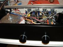
I wanted to let you guys know I finished with the 2-channel PA100 gainclone. Thanks for everyone's help. A lot of credit goes to alexw88 since I got a lot of good ideas from his site and I based my pcb design on his
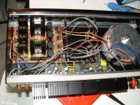
The amp sounds great, I'm really happy with it. I'll post a few pics to this thread... I had a bit of trouble with the power supply (see here ). I don't think Carlos' PS is up to the task, not when it only has 4-5V of headroom to regulate with. I had a lot of voltage dropouts on the negative voltage rail until I added a current dumping bypass transistor. That fixed the problem. For some reason, there were never any issues with the positive voltage rail. I am assuming the chip amps draw more current from the negative rail (?)
The heatsinks were a great buy at $3 a piece. They are quite adequate for the task, since even at excessive volume levels they don't really get hot. The pots are Taiwan-Alpha's sourced from Mouser. These were recommended in a Peter Daniels thread somewhere, I don't have anything to compare them to, but the amp sounds quite nice and the pots were pretty cheap.
I wanted to let you guys know I finished with the 2-channel PA100 gainclone. Thanks for everyone's help. A lot of credit goes to alexw88 since I got a lot of good ideas from his site and I based my pcb design on his
The amp sounds great, I'm really happy with it. I'll post a few pics to this thread... I had a bit of trouble with the power supply (see here ). I don't think Carlos' PS is up to the task, not when it only has 4-5V of headroom to regulate with. I had a lot of voltage dropouts on the negative voltage rail until I added a current dumping bypass transistor. That fixed the problem. For some reason, there were never any issues with the positive voltage rail. I am assuming the chip amps draw more current from the negative rail (?)
The heatsinks were a great buy at $3 a piece. They are quite adequate for the task, since even at excessive volume levels they don't really get hot. The pots are Taiwan-Alpha's sourced from Mouser. These were recommended in a Peter Daniels thread somewhere, I don't have anything to compare them to, but the amp sounds quite nice and the pots were pretty cheap.
Attachments
and for posterity...
here's a link to my site where I documented the construction of the amp... could be useful to anyone who encounters this thread later on. perhaps I'll add a link to my sig.
2-channel pa100 gainclone
here's a link to my site where I documented the construction of the amp... could be useful to anyone who encounters this thread later on. perhaps I'll add a link to my sig.
2-channel pa100 gainclone
Hi guys,
One question: what would happen in terms of sound if I just used a regular power supply with this amp?
It's kind of hard to find the regulator in my country and also I got a lot of caps from a couple of dumpster dives so I can definitely put as much as I need in the supply. If this is OK, how much should I put?
>>>>http://fluxforge.com/audio/gainclone.htmlThis domain name expired on 04/27/06 and is pending renewal or deletion
Sorry guys, I've been AWOL. The site moved to here:
http://spandexter.com/audio/gainclone.html
You don't need that specific regulator, just anything that meets the same specifications (I forget how many amps this thing pulls during peak) and can regulate at ~35 volts. The circuit that biases the regulator will change if you use a different one, but it's the functionality that matters.
- Status
- This old topic is closed. If you want to reopen this topic, contact a moderator using the "Report Post" button.
- Home
- Amplifiers
- Chip Amps
- 2-channel parallel 100W GC using LM3886