Yes, same capacitance. I tried also more with LM4780 ( by adding 5,600u on each side) but the effect was similar to what happens with LM3875.
Some suggest that for a sub amp it's recommended to add more capacitance. What I noticed so far, the amount of bass increases indeed, but the quality is under question mark. The bass is usually boomy, loosing tightness and definition.
Some suggest that for a sub amp it's recommended to add more capacitance. What I noticed so far, the amount of bass increases indeed, but the quality is under question mark. The bass is usually boomy, loosing tightness and definition.
Peter Daniel said:Yes, same capacitance.
The difference is that you are using 1,500uf per channel/chip on the LM3875, but that capacitance is shared by two channels on the LM4780.
That's why the LM4780 is not producing tight bass.
Also, there's a point when adding more capacitance affects the midband and treble.
My point is, the LM3886 and, specially, the LM4780 needs a different approach in PSU design.
There's also no use in paralleling LM4780s if the PSU is not up to the task, no matter what VA rating is the trafo, IMHO.
Peter Daniel said:Yes, same capacitance. I tried also more with LM4780 ( by adding 5,600u on each side) but the effect was similar to what happens with LM3875.
Some suggest that for a sub amp it's recommended to add more capacitance. What I noticed so far, the amount of bass increases indeed, but the quality is under question mark. The bass is usually boomy, loosing tightness and definition.
My experience with two 3886 setups was:
1) The bass with 1000uF per chip (1000 for V+, 1000 for V-) was boomy and with little tightness and definition. Mid and treble was great.
2) The bass in the other setup, using 4700uF per chip, was very tight and controlled. Mid and treble was average.
Perhaps the 4780, being two 3886 chips inside, may work better starting at 2200uF per chip (2200 for V+ and 2200 for V-).
Carlos
Hi,carlmart said:
1) The bass with 1000uF per chip (1000 for V+, 1000 for V-) was boomy and with little tightness and definition. Mid and treble was great.
2) The bass in the other setup, using 4700uF per chip, was very tight and controlled. Mid and treble was average.
Would you recommend trying paralled 1,000uF caps?
I have a bag of them.
Also, as I feel I can take your word for it, can you recommend a circuit for a starter 3886 amp? (by starter I mean simple, that can later be improved upon by addition of a buffer and/or regulated psu).
Thanks,
Simon
carlmart said:My experience with two 3886 setups was:
1) The bass with 1000uF per chip (1000 for V+, 1000 for V-) was boomy and with little tightness and definition. Mid and treble was great.
2) The bass in the other setup, using 4700uF per chip, was very tight and controlled. Mid and treble was average.
Perhaps the 4780, being two 3886 chips inside, may work better starting at 2200uF per chip (2200 for V+ and 2200 for V-).
Carlos
Precisely.
But there's a trick that allows you to use as much capacitance as you want, with unregulated PSU, and very good results.
I've posted that.
Also, the caps on the chip's PSU pins should be small, not thousands of uf, but around 100uf.
To Simonty Pioneer in PSU have 10000uF paralleled with 2x4700uF with 100nF on each cap paralleled with 10ohm in serial with 100nf on + rail, same on -. I change output transistors with Toshiba devices and bias is setting to 100mA. Sound is very good. Same type PSU is on lm3886 and TDA, but TDA sounds much better.
stex said:To Simonty Pioneer in PSU have 10000uF paralleled with 2x4700uF with 100nF on each cap paralleled with 10ohm in serial with 100nf on + rail, same on -. I change output transistors with Toshiba devices and bias is setting to 100mA. Sound is very good. Same type PSU is on lm3886 and TDA, but TDA sounds much better.
Change that 10 ohm resistor with 1 ohm, on the LM3886 PSU.
Thanks for the info.stex said:To Simonty Pioneer in PSU have 10000uF paralleled with 2x4700uF with 100nF on each cap paralleled with 10ohm in serial with 100nf on + rail, same on -. I change output transistors with Toshiba devices and bias is setting to 100mA. Sound is very good. Same type PSU is on lm3886 and TDA, but TDA sounds much better.
I'll try not to expect too much from a basic LM3886 setup then! It would have to be half-decent to outdo my Roksan Caspian... but it would be great to sell that, and go active!
I too would be most grateful to see such helpful info.steenoe said:Carlos Filipe; could you point at your PSU trick??
Steen.
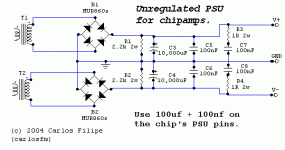
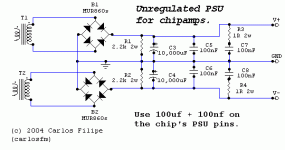
The trick for using high-capacitance unregulated PSU without mucking up the sound is the snubber, with the values you can see on my schematic below.
The values are critical, these give me very good results.
After the snubber, of course, there should not be big caps.
On the chip, use 100uf, and I recommend bypassing them at the chip's pins with 100nf.
Here it is:
The values are critical, these give me very good results.
After the snubber, of course, there should not be big caps.
On the chip, use 100uf, and I recommend bypassing them at the chip's pins with 100nf.
Here it is:
Attachments
steenoe said:I have a bunch of Rifa PHE450 100nF,
I suppose they will do? (Metalized polypropylene)
Steen.
Those will do fine.
Thanks very much for the schematic. I'll probably be using that to try this thing out.carlosfm said:The snubber is, of course, between each rail and ground.
I can't see any difference between your first and second pic tho! I'm tired

SimontY said:I can't see any difference between your first and second pic tho! I'm tired
It's a small black dot that joins C7 and C8 to ground.
That black dot was missing.
I know from experience that if the schematics are not very clear someone sooner or later would ask.
Worse than that is making, and later... asking.

Ahh, now I see it! Thankscarlosfm said:
It's a small black dot that joins C7 and C8 to ground.
That black dot was missing.
I know from experience that if the schematics are not very clear someone sooner or later would ask.
Worse than that is making, and later... asking.
Carlosfm provided a great tip on his suggestion to add a zobel filter to the supply.
That filter can really clean up the inductance of large capacitors, which is probably part of the problem when using bigger than 1000uF capacitors there.
Here's an interesting reading about power supply design, by Dejan Veselinovic:
http://www.zero-distortion.com/techno/powersupply/powersi.htm
Part 7 explains how to implement these filters on most amplifiers, even if the values Dejan suggests are a little different from Carlos'. I would start first with the values Carlos tried, as tuning may be critical.
The article also suggests putting this filter close to the power devices, in our case the 3886.
Carlos is probably a bit generous with the results you can get from these filters when compared with the regulator, but it would probably make differences not so large between regulated and unregulated supplies.
Carlos
carlmart said:Carlosfm provided a great tip on his suggestion to add a zobel filter to the supply.
That filter can really clean up the inductance of large capacitors, which is probably part of the problem when using bigger than 1000uF capacitors there.
That's it.
carlmart said:Carlos is probably a bit generous with the results you can get from these filters when compared with the regulator, but it would probably make differences not so large between regulated and unregulated supplies.
No, I didn't say it's better than regulated.
It's just easier to implement, with very good results too.
Also, if you go bridge/parallel, regulators start to be unpractical, because they can't feed a bunch of chips.
Of course one can use bypass transistors, but things start to get massive...
BTW, I started with the values Dejan proposed, but in this case the values I ended up using were the ones that gave me the best sonic results.
Carlos, I think you missed this thread?
http://www.diyaudio.com/forums/showthread.php?s=&threadid=43423
EDIT: oh, another thing: I could use the snubber on the chip, but it's not practical (and wise, I should say), I prefer to have the small caps (100uf+100nf) as near as possible to the chip's PSU pins.
Once again we are completely in agreement.
Yes, I missed that thread because I was abroad and not reading the daily forum news.
On many occasions I had mentioned Dejan's articles on this Forum, particularly the one on PSUs, because they had very valuable and practical information for DIYers.
I just don't quite see why do you say that regulators would be a problem if you go bridge/parallel, except for the current a combo would demand, of course. Parallel arrangements should do fine. For larger currents a discrete type might be in order perhaps.
It may no be practical indeed to put the snubbers close to the chipamps, though I wonder if it won't make a difference. I will see if I can try and report back here.
Some tests I had programmed for the last weeks had to be postponed, but I hope to get back with news soon.
Carlos
- Status
- This old topic is closed. If you want to reopen this topic, contact a moderator using the "Report Post" button.
- Home
- Amplifiers
- Chip Amps
- LM3875 vs LM3886 vs LM4780

