Hi,
I created a schematic according to the information in this post:
http://www.diyaudio.com/forums/showthread.php?s=&threadid=16928&perpage=10&highlight=&pagenumber=1
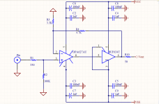
Below is the attached schematic.
Is this correct?
Carlos, can you shed some light on this?
I created a schematic according to the information in this post:
http://www.diyaudio.com/forums/showthread.php?s=&threadid=16928&perpage=10&highlight=&pagenumber=1
Below is the attached schematic.
Is this correct?
Carlos, can you shed some light on this?
Attachments
Footnote
Hi,
Yes this is correct, just as Carlos stated later in his post's on this circuit. It's taken from the application footnotes from Nat Semi's web site..
Iv'e built the heaphone amp and it works fine , albeit with some minor fault's. But thats down to my circiut layout..it's got a small hummmm, apart from that im pleased with it.
Try Pavel Macura site...
D_GR8_1 said:Carlos, can you shed some light on this?
Me?

Oh.
C2, C4, C7 and C9 should be 100nf poly or ceramic, not 1uf.
Also, you need a cap between pins 2 and 6 of the OPA627.
200pf is fine, but you can test lower values, like 100pf, it also works fine.
Avoid ceramics here.
An importand thing is that all the PSU bypass caps (100uf+100nf) should be on each chip's PSU pins to ground.
You can also use a 100~330nf poly cap from - to + PSU pins on the OPA627, under the circuit.
It is very important that the layout is as small/tight as possible.
No big feedback loop, no PSU bypass caps far from the chip's PSU pins.
If you stricktly follow these instructions you will have a gorgeous sound.

improved it
Carlos,
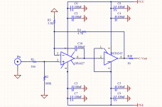
I followed you suggestions and improved the schematic.
You mention to use a poly cap between - and + pins. Should it be polarized or non-polarized?
About the track length and distance, I will try and implement that onto the PCB design.
I will post the PCB here in the next few days.
Thanks.
Carlos,
I followed you suggestions and improved the schematic.
You mention to use a poly cap between - and + pins. Should it be polarized or non-polarized?
About the track length and distance, I will try and implement that onto the PCB design.
I will post the PCB here in the next few days.
Thanks.
Attachments
Re: improved it
Are you sure you wanna do this?
D_GR8_1 said:You mention to use a poly cap between - and + pins. Should it be polarized or non-polarized?
Are you sure you wanna do this?
Swedish Chef said:The day you find a polarized poly cap you have indeed found a very exotic "audio grade" cap...

Re: Re: CarlosFM's Buffer. Is it correct?
You mean C2,C4,C3 and C5. Right?
Shusha
carlosfm said:
C2, C4, C7 and C9 should be 100nf poly or ceramic, not 1uf.
You mean C2,C4,C3 and C5. Right?
Shusha
Re: Re: Re: CarlosFM's Buffer. Is it correct?
No.
I meant what I meant.
shusha said:You mean C2,C4,C3 and C5. Right?
Shusha
No.
I meant what I meant.
If I wanted to make an integrated preamp/GC in one chassis, I wouldn't need the BUF634T, right? Would I just leave off the BUF stage, or does the OPA627 need an output resistor as well?
Would this be the way to go or does the circuit sound better with the BUF behind the OPA?
Thanks,
KT
Would this be the way to go or does the circuit sound better with the BUF behind the OPA?
Thanks,
KT
Re: Re: Re: Re: CarlosFM's Buffer. Is it correct?
Sorry Carlos I just realized that this is not your original schematics but modified one.
C2, C4, C7 and C9 should be 100nf poly or ceramic you said, while schematics shows that 7&9 are polarized.
shusha
carlosfm said:
No.
I meant what I meant.
Sorry Carlos I just realized that this is not your original schematics but modified one.
C2, C4, C7 and C9 should be 100nf poly or ceramic you said, while schematics shows that 7&9 are polarized.
shusha
Re: improved it
I would like to build this circuit as a Pre-Amp, would i need to change anything if i use a 50k pot?
D_GR8_1 said:Carlos,
I followed you suggestions and improved the schematic.
I would like to build this circuit as a Pre-Amp, would i need to change anything if i use a 50k pot?
PMA said:Carlos,
my sincere congratulations to your circuit
Pavel
It is not my circuit.
It's on the datasheet, and the first time I saw it here it was posted by you, as a buffer.
So, the credit must go to you.
I don't have any problem to give the credit to where it belongs, I don't understand your post.
I didn't open this thread, I didn't give it the title it has, I didn't claim anything.
Someone asked my help.
Is it clear?
Also, I'm not selling anything, and I find your "insinuation" offensive.
Re: improved it
I have a 50k Alps pot could i use it in this circuit? Would any changes be needed?
Was thinking of building this as a Pre-Amp.
D_GR8_1 said:Carlos,
I followed you suggestions and improved the schematic.
You mention to use a poly cap between - and + pins. Should it be polarized or non-polarized?
About the track length and distance, I will try and implement that onto the PCB design.
I will post the PCB here in the next few days.
Thanks.
I have a 50k Alps pot could i use it in this circuit? Would any changes be needed?
Was thinking of building this as a Pre-Amp.
Attachments

I don't understand why would you consider a buffer like this and leave out an option for differential inputs?
I understand your "present" need may not require it, but it would be such a waste to not implement it for future use.
Especially considering the minimal cost to add differential inputs.
I understand your "present" need may not require it, but it would be such a waste to not implement it for future use.
Especially considering the minimal cost to add differential inputs.
Simulated
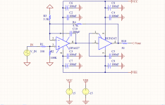
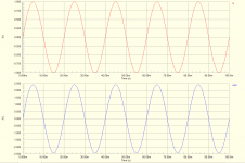
I just ran a simulation of this buffer circuit.
The input was 1V/50Hz sine, the output was 2.5V/50Hz sine.
Which means that the signal was multiplied by 2.5.
This being a buffer, there should be no multiplication, right?
Anyhow, here is the schematic:
I just ran a simulation of this buffer circuit.
The input was 1V/50Hz sine, the output was 2.5V/50Hz sine.
Which means that the signal was multiplied by 2.5.
This being a buffer, there should be no multiplication, right?
Anyhow, here is the schematic:
Attachments
- Status
- This old topic is closed. If you want to reopen this topic, contact a moderator using the "Report Post" button.
- Home
- Amplifiers
- Chip Amps
- CarlosFM's Buffer. Is it correct?