Hi All-
Quick question on heat sinking regulators.
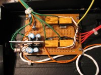
I have a +/- 17 VDC supply feeding some 7815 and 7915 regulators and then some 7812 and 7912 regulators mounted back to back. I did that thinking there would not be much current since they are powering relay coils and an OPA627 buffer.
I put the "bar" there to hang a larger heat sink on if needed, and the regs are insulated from the bar and each other.
So the question is:
What type of heat is expected from the regs loafing around?
Any insight into this would be helpful.
Edit: I forgot to mention that if any of the four the relays are energised then a standard red LED associated with that relay is powered from the +12 rail also. again, minimal, but I figured I better mention.
Quick question on heat sinking regulators.
I have a +/- 17 VDC supply feeding some 7815 and 7915 regulators and then some 7812 and 7912 regulators mounted back to back. I did that thinking there would not be much current since they are powering relay coils and an OPA627 buffer.
I put the "bar" there to hang a larger heat sink on if needed, and the regs are insulated from the bar and each other.
So the question is:
What type of heat is expected from the regs loafing around?
Any insight into this would be helpful.
Edit: I forgot to mention that if any of the four the relays are energised then a standard red LED associated with that relay is powered from the +12 rail also. again, minimal, but I figured I better mention.
Attachments
You should estimate the worst-case current drawn through the regulators (you might be able to measure that with a multimeter), multiply that by the worst-case voltage drop across them (be sure to account for mains voltage fluctuations) to get the maximum power they might have to dissipate (call it P) assume the worst-case ambient temperature (Tamb) (50C will usually leave a good margin of safety). Usually the maximum allowed junction temperature is 150C (Tj), but check the datasheet to be sure. Then the maximum allowed thermal resistance (Rth) will be:
Rth = (Tj - Tamb) / P
That will be the total, including junction-to-case thermal resistance, and that of the case-to-heatsink interface. The first of those will be in the datasheet for the regulator (it might be about 3C/W for a TO220 device), the second depends on the mounting method. Uninsulated and using silicone thermal paste you might expect about 0.1-1.0C/W depending on how well bolted down they are. It will be higher if you are insulating them. Subtract those from the total to get the maximum thermal resistance of the heatsink.
I expect the simple metal bar in your picture would be adequate on its own for small currents, but it pays to do the calculations to be sure.
IMO, your heatsinks should be fine.
fire them up and let them run for a while to monitor if they ever become hot. my heatsinks are not even warm at all.
i used +/- 15v for each channel to drive opa627/buf634 combo.
one psu:
my preamp:
fire them up and let them run for a while to monitor if they ever become hot. my heatsinks are not even warm at all.
i used +/- 15v for each channel to drive opa627/buf634 combo.
one psu:
An externally hosted image should be here but it was not working when we last tested it.
my preamp:
An externally hosted image should be here but it was not working when we last tested it.
Hey Garbage-
Thanks for the input.. I'm still trying to sort out the formula from Mr. Evil's post . I'M joking Mr. Evil... Really, I'm just in a good mood this evening and feeling feisty.
Anyway, back to the subject.. Garbage, I was curious to see what you thought of the opa627/buf634 combo.
I read the paper on it and though I would like to try it. In this instance I did not need the second device but I will be building a pre-amp that I may try it in.
Thanks for the input.. I'm still trying to sort out the formula from Mr. Evil's post
. I'M joking Mr. Evil... Really, I'm just in a good mood this evening and feeling feisty.Anyway, back to the subject.. Garbage, I was curious to see what you thought of the opa627/buf634 combo.
I read the paper on it and though I would like to try it. In this instance I did not need the second device but I will be building a pre-amp that I may try it in.
Hey digi01-
It is an output switcher. It is to distribute one input to 1-4 outputs.
And no the layout is crap, but for proto-typing with perf board and p-2-p wiring it will have to do.
I put two stages of regulation to ensure a stable pwr supply for the OPA627 because the user requested the buffer add NOTHING to the signal. It is only there to help the signal not lose anything when being sent to multiple devices.
If he likes the sound I will then have PCB's made to miniaturize it and change packages on the buffer to a surface mount. Also I will change the relays to 5-volt versions and move to 9 and 5-volt pwr rails instead of the current 15/12.
Edit: Yellow wire is signal in, white wires are signal to each relay, blk is out the relays, red is out the box. There are jumpers to route the signal to/from the buffer so it can be by-passed entirely if the guy doesn't like the "sound" of it (musicians, VERY finicky).
rabstg said:
Anyway, back to the subject.. Garbage, I was curious to see what you thought of the opa627/buf634 combo.
prior to this, i was using a passive preamp.
with the opa627/buf634 combo, this preamp became active.
the difference is very noticable in the bass. the bass goes lower and is tight. highs are not harsh when playing emi fujita's camomile album.
with a dual mono supply, separation of instruments is clearer.
here's my thread on it.
cheers
garbage
rabstg said:
It is an output switcher. It is to distribute one input to 1-4 outputs.
the guy doesn't like the "sound" of it (musicians, VERY finicky).
your friend is a musicians?wow
") I have this hobby too.
I have this hobby too.I have build a PC based systems at home,here is my home studio.
I have diy some interface module to connect all parts,such as signal console,midi bridge,and micphone preamp.
Hi All-
Well I fired it up and after a few seconds the heat sinks got HOT .
.
I measured the voltage going to them (I measured +- 19 at the PSU) and I had 3 volts on the 7912 and -5 on the 7812... Oops.
The jumper from the input power connector to the PCB was reversed sending the + voltage to the 79xx rail and the - voltage to the 78xx rail..
Swapped them and it came up great. No heat since.
I have left it on for several multi hour sessions and still no smoke.
Thanks everyone who confirmed and responded to my concern about the proper heat sinking.
Well I fired it up and after a few seconds the heat sinks got HOT
.I measured the voltage going to them (I measured +- 19 at the PSU) and I had 3 volts on the 7912 and -5 on the 7812... Oops.
The jumper from the input power connector to the PCB was reversed sending the + voltage to the 79xx rail and the - voltage to the 78xx rail..
Swapped them and it came up great. No heat since.
I have left it on for several multi hour sessions and still no smoke.
Thanks everyone who confirmed and responded to my concern about the proper heat sinking.
- Status
- This old topic is closed. If you want to reopen this topic, contact a moderator using the "Report Post" button.
- Home
- Amplifiers
- Chip Amps
- Required heat sink