And it works very well. Thanks to all for their ongoing help- I read a lot of these threads and have learned quite a bit. I used boards from BrianGT, and I very much appreciate his efforts. Thanks also to Nuuk, great website. Too many others to mention.
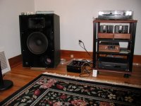
Construction details: The bottom of the chassis is something I found in the garbage, maybe some old scientific equipment. The sides are 3/8" aluminum bar that I polished up. They look good, but also serve as heatsinks. The front is from a $500,000 spectrometer that was dismantled here at school.
When I make a lid, it'll probably be from wood. I don't know how hot this thing will run, so I don't have a good idea of how much vent I need yet.
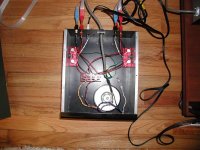
The guts are standard- dual 20V toroid from avel lindel (sp?), mur860 diodes- I did add a Z5U ceramic cap across each power supply electrolytic. The power supply output is a very clean DC- less than 3 mV AC. Resistors are stock from Brian. Next time I'm going to turn the gain down- it's too much for me.
They sound pretty good- clean and bright at the moment. There's no discernable background noise when listening with the ipod as a source. With the tube preamp hooked up, it's somewhat microphonic and I think there must be a ground loop because there is a slight hum that's not present with my other amps.
Now a question- On the inputs, I have the S and the SG going to the boards. That's ok. Should I run a ground from the signal jack to the chassis ground as well? Might that take care of a ground loop when I hook it up to the tube preamp?
Cheers,
Jason
Construction details: The bottom of the chassis is something I found in the garbage, maybe some old scientific equipment. The sides are 3/8" aluminum bar that I polished up. They look good, but also serve as heatsinks. The front is from a $500,000 spectrometer that was dismantled here at school.
When I make a lid, it'll probably be from wood. I don't know how hot this thing will run, so I don't have a good idea of how much vent I need yet.
The guts are standard- dual 20V toroid from avel lindel (sp?), mur860 diodes- I did add a Z5U ceramic cap across each power supply electrolytic. The power supply output is a very clean DC- less than 3 mV AC. Resistors are stock from Brian. Next time I'm going to turn the gain down- it's too much for me.
They sound pretty good- clean and bright at the moment. There's no discernable background noise when listening with the ipod as a source. With the tube preamp hooked up, it's somewhat microphonic and I think there must be a ground loop because there is a slight hum that's not present with my other amps.
Now a question- On the inputs, I have the S and the SG going to the boards. That's ok. Should I run a ground from the signal jack to the chassis ground as well? Might that take care of a ground loop when I hook it up to the tube preamp?
Cheers,
Jason
Attachments
The bottom of the chassis is something I found in the garbage,
Nice work Jason. I see my philosophy is rubbing off on you!

Dave,
The other two pairs of wires- consider them as pairs (each pair carries 20 V). One pair goes to one half of the rectifier board, the other pair goes to the other half of the recifier board.
Wire the ones that have the • on it (marked on the transformer) to the AC1 H and AC2 H on the board. Wire the other pair to the AC1 N and AC2 N.
On my transformer, red is H (•), black is N (first pair), and orange is H (•) and yellow is N (second pair)
So, I soldered red to AC1 H, black to AC1 N. Then I soldered orange to AC2 H and yellow to AC2 N. If your transformer is different, follow the 'dot' code, not my colors.
Costiss,
Thanks- I haven't tied SP 0V to ground. I'll try that.
Nuuk,
I'm definately a cheap date.
Cheers,
Jason
- Status
- This old topic is closed. If you want to reopen this topic, contact a moderator using the "Report Post" button.
- Home
- Amplifiers
- Chip Amps
- Yet another new Gainclone (YANG?)