GainClone Bridge or Parallel? Which one sounds good? The following are the combinations possible. I am confused which one to choose.
1. Bridge connection
2. Parallel connection of two inverting
3. Parallel connection of two non-inverting
I have been reading a lot about GainClone LM3886 here. I gather from other's opinion that Inverting always sounds good. The confusion is that if that is true then which one will sound good 1 or 2?
Now I have all the parts to build my dream project, the reason why I became member of this forum. I plan to have both buffer and DC-servo in the circuit. I am reading the application notes AN-1192 also. But it will be helpful to listen to experienced people.
Looing forward to your suggestion.....
1. Double the volts but if your speakers impedance dips - current starvation. Bridge + parallel is a better plan.
2/3 Differences between invering/non-inverting are a bit exaggerated. Parallel is very likely better with 90% of 'modern' speakers. Precise matching of resistors and offset trimming are a must.
Buffered is probably fine if you can build a good buffer. Servo is simply not needed with these chips. If you have input offset rather use capacitor/transformer than a servo.
Thanks analog_sa for your reply. At the moment I am just reading and reading in different threads. Here is a rough plan of my stereo Gain Clone design for one chanel.
1. Parallel of two inverting LM3886TF design with 0.1% resistors.
2. DC-servo using AD8620 or LF412. Though people say that DC-servo is not necessary, but all the good designs have them.
3. Separate buffer for each inverting stage using OPA627. This is somthing new I am planning which I have not seen before.
Any suggestions or opinion are wellcome...
Once I am finished with the circuit I will post that in the forum for opinion and corrections.
I suggest you look at the app notes in the data sheet for the LM4780. In particular the THD+N graphs comparing bridge mode with parallel mode. You will notice the parallel arrangment has worse THD+N in almost every case. I have no idea why - maybe the inherent symmetry of the balanced topology helps eliminate crossover distortion ?
At any rate, thats why I've chosen to build using bridge mode.
At any rate, thats why I've chosen to build using bridge mode.
Franz G said:... I recommend you a t-network for feedback!
Franz
TwoSpoons said:I suggest you look at the app notes in the data sheet for the LM4780. In particular the THD+N graphs comparing bridge mode with parallel mode. You will notice the parallel arrangment has worse THD+N in almost every case. I have no idea why - maybe the inherent symmetry of the balanced topology helps eliminate crossover distortion ?
At any rate, thats why I've chosen to build using bridge mode.
Thanks for the suggestions. I will look at t-network and the app notes of LM4780 and get back soon. The application notes AN-1192 suggests that the best design is first parallel and then bridge. But I do not want to build so big a amplifier at the moment. And then I got confused about choosing from bridge and parallel.
I will look at t-network
I am sure, it will be an advantage with the t-net even with bridged and/or paralleled amps, as the chips have the same parasitic capacitances.
Edit: I just had a look into AP1192: the t-net seems specially interesting for the bridged version: with the t-net you could use the same input-Z for the inverting amp like the noninverting amp!
This should boost the quality of an bridged amp!
End of Edit...
You will not be disapointed about this detail!
Franz
TwoSpoons said:I suggest you look at the app notes in the data sheet for the LM4780. In particular the THD+N graphs comparing bridge mode with parallel mode. You will notice the parallel arrangment has worse THD+N in almost every case. I have no idea why - maybe the inherent symmetry of the balanced topology helps eliminate crossover distortion ?
At any rate, thats why I've chosen to build using bridge mode.
I have looked at the datasheet of LM4780. I think the following two procedures will give different performance:
1. parallel connection of two separate inverting LM3886.
2. parallel connection of two inverting amplifiers (equivalent of LM3886) in LM4780.
The reason I feel is the length of some paths will be more in 1 than 2.
Franz G said:
I am sure, it will be an advantage with the t-net even with bridged and/or paralleled amps, as the chips have the same parasitic capacitances.
Edit: I just had a look into AP1192: the t-net seems specially interesting for the bridged version: with the t-net you could use the same input-Z for the inverting amp like the noninverting amp!
This should boost the quality of an bridged amp!
End of Edit...
You will not be disapointed about this detail!
Franz
I just noticed a thread on t-network. Have not yet explored it fully. Many many people seem to be interested in t-network. I will also try it in my circuit and post here the result.
Thanks for telling me about it.
A curiosity: feedback resistor should be as close to the chip as possible. and the track to it be as short possible. even using SMD is suggested. I am just wandering that using a t-network will make both the track and the total path length more. will a t-network also solve this problem of closeness; I mean with a t-network one need not bother to make the path length least possible. I am now thinking of a t-network with SMD.
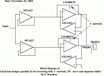
Block diagram of my design
I am posting the block diagram of my gainclone design using LM3886.
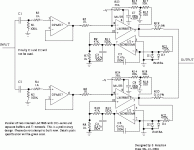
More details schematic will come soon. Please have a look and give me your suggestions....I will include acknowledgments and thanks to all the people I got help and suggestions form when I post the detals schematic....
I am posting the block diagram of my gainclone design using LM3886.
More details schematic will come soon. Please have a look and give me your suggestions....I will include acknowledgments and thanks to all the people I got help and suggestions form when I post the detals schematic....
Attachments
I am following the application notes AN-1192. Yeah, I will try the circuit without the DC-servo also. I see in AN-1192 that in the case of parallel of two inverting design the cap between buffer and the amp is used only when there is no DC-servo. I think that is what you mean.
regards
regards
no mistake found so far...it seems....so i can go ahead and build it. this is the only way i can test it since simulation is not possible in my computer.
here are the people i would like to thank for helping me directly or indirectly....
analog_sa, ashok, Franz G, TwoSpoons, carlmart, richie00boy, peranders, gmphadte.
here are the people i would like to thank for helping me directly or indirectly....
analog_sa, ashok, Franz G, TwoSpoons, carlmart, richie00boy, peranders, gmphadte.
Upupa Epops said:Only little notice : Input buffer can be common for both amps. Voltage divider on output of servo is too high - give there ten times lower value - 4K7 and 10 K.
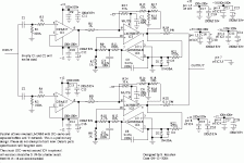
i am experimenting with separate buffers. i know this makes the circuit expensive to build. but i have all the ics needed, so i will try. thanks for the suggestion about voltage divider resistors. i reduced it according to your suggestion. a little update of the circuit is attached. i will have lm338 regulated power supply for lm3886 and lm317/lm337 regulated for opa627 and ad8620ar. the power supply design will be posted shortly.
still waiting for more suggestions/corrections before i design the PCB.
- Status
- This old topic is closed. If you want to reopen this topic, contact a moderator using the "Report Post" button.
- Home
- Amplifiers
- Chip Amps
- Bridge or Parallel?


