I dont understand the ratings too well but this falls within the specs for Brian GT's LM3875 kit
http://custom1.farnell.com/cpc/prod...rs+and+Inductors+-+Toroidal&product_id=275506
I cant find a definitive heatsink requirment...
Will this do?
http://www.conradheatsinks.com/products/flat100_350.html#MF15
the 75mm one has a thermal resistance on 0.72 C/Watt for 80C rise. They will only cost about £5.50 eachplus shipping.
Oh an internal wiring...as I only intend to make these once what is the ultimate? Silver, pure crystal copper, etc etc......?
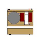
Don't laugh too hard at the naff drawing.......
This is what I hope the units will look like when finished (her har har no not as bad as the drawing!!!)
The chasis will be made of wood (something real nice) as my metal working skills and the lake of good looking reasonably priced high WAF metal cases are far and few between.
The layout was inspired by conrad-johnson's Premier 350.
Power in one side and running through to the outputs with the heatsinking at one end...keeping all powe parts away from the source input/amp board.
The heatsink should screen the amp from the power supply but I may also layer the inside with copper leaf(?) to help.
Attachments
JRKO said:Don't laugh too hard at the naff drawing.......
This is what I hope the units will look like when finished (her har har no not as bad as the drawing!!!)
The chasis will be made of wood (something real nice) as my metal working skills and the lake of good looking reasonably priced high WAF metal cases are far and few between.
The layout was inspired by conrad-johnson's Premier 350.
Power in one side and running through to the outputs with the heatsinking at one end...keeping all powe parts away from the source input/amp board.
The heatsink should screen the amp from the power supply but I may also layer the inside with copper leaf(?) to help.
CPU heatsink are quite good for this job.
An externally hosted image should be here but it was not working when we last tested it.
they are a little bit over room temp. and my Gc is feeded with a 300Va 2x25V Tx.
Marc
from those pictures the heatsinks I have specified may be too large....but I also need them that size for cosmetic reasons. Will that be a problem?
Is the wooden chassis ok? How do you ground it or is that not required? Is the copper leaf a good idea? What about internal wiring?
Is the wooden chassis ok? How do you ground it or is that not required? Is the copper leaf a good idea? What about internal wiring?
JRKO said:from those pictures the heatsinks I have specified may be too large....but I also need them that size for cosmetic reasons. Will that be a problem?
 No, of course not. A bigger heatsink never hurts...
Is the wooden chassis ok? How do you ground it or is that not required? Is the copper leaf a good idea?
Wood as an enclosure is okay! OTOH, the copper is a very good idea for shielding (isolating against induced noise). I would recommend it, but it will produce a little work to get the shielding 'tight'.
What about internal wiring?
At first, you're not showing a primary fuse, nor a mains switch.
For wiring the mains jack, switch, fuse and transformer primary, I'd recommend a stripped and crimped wire that fulfills all the usual standards and regulations for mains wiring, e.g. a piece of good mains wire.
On the secondary side, I recommend using the same type of wire between transformer/rectifier, rectifier/amp and amp/speaker. I use quality speaker cable with a cross section of at least 2.5qmm, but 1.5qmm will also work. Which brand/type you choose is up to your taste.
Try to keep the double insulation on the primary side, e.g. leave the cable sleeve on, put shrink tube around contacts and connectors, etc.
Hope this helps,
Sebastian.
Thanks for the reply sek.
I'll use the wiring thats on the transformer from the power socket to transormer and the attached secondary cables to the rectifier boards. Is it wise to always have a power switch? I may just power it up from the mains.
From there I'll need to make sure the cable can fit inside the front of the casinf to pass the heatsink.
Shouldn't the input wiring be fairly good quality cable?
The output will probably be come kimber 8tc as this is what I will probably be using to connect my loudspeakers.
As the amp and power sections are in different compartments and the heatsink is between the transformer and the amp I thought I would copper line the amp compartment only.
I'll use the wiring thats on the transformer from the power socket to transormer and the attached secondary cables to the rectifier boards. Is it wise to always have a power switch? I may just power it up from the mains.
You do not have to uuse a power switch bity it won't do any harm. You must use a fuse or circuit breaker on those primary connections though.
If you haven't done so yet, have a look at my GC FAQ pages.
(How many times have I typed that now?
 )
)Nuuk said:
If you haven't done so yet, have a look at my GC FAQ pages.
(How many times have I typed that now?
Maybe it should be your sig?
Thanks Nuuk et all
I think I'll go with the fused but no switch version.
Whats the best input wiring? I assume that using the same cable for output as between amp and speakers is a good idea?
To iliminate another connection in the line couldn't I just have long (2m) cable comming from the amp to be connected direct to my speakers? Thats 4 extra non soldered connections removed!
Whats the best input wiring?
As for the mains input, there's no wire left if you use, say, an IEC inlet with built in fuse holder.
For the audio input, I recommend shielded wire of the same quality as you would use for external interconnects. It's just a couple of inches, so why not take the best you have?
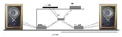
To iliminate another connection in the line couldn't I just have long (2m) cable comming from the amp to be connected direct to my speakers?
No reason why you couldn't, other than that it would reduce your amp's flexibility (what about those speakers 2.5m away... okay, but those, 2.75m away...).
Cheers,
Sebastian.
Now why didn't I think of that?
It won't help. Because you will have to tell everyone to have a look at your signature now.
Sebastian.
PS: But it certainly makes things easier for us others. We now don't have to give a link to DD, but can just recommend to do a search for one of Nuuks posts and have a look at it's signature!

To iliminate another connection in the line couldn't I just have long (2m) cable comming from the amp to be connected direct to my speakers? Thats 4 extra non soldered connections removed!
There's no harm in in trying to improve every aspect of your hi-fi! But IMHO, it can be counterproductive to do what you are suggesting. For instance, soldering those speaker cables will inhibit you from trying different types of cable, or at least make a quick change of cable impossible.
And I'm not quite sure how soldered speaker cables are preferable if you want to experiment with passive and active crossovers?

It won't help. Because you will have to tell everyone to have a look at your signature now.
Sek, we have a saying in the UK - 'Many a true word is spoken in jest'!
- Status
- This old topic is closed. If you want to reopen this topic, contact a moderator using the "Report Post" button.
- Home
- Amplifiers
- Chip Amps
- Transformer & Heatsink