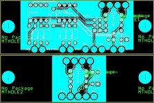
Designed with input from BrianGT, here is a preliminary bridging board. There are two versions:
The first [upper] version, allows a jumper to be placed across the 2x6 pin header. This will allow either direct connection to the line driver chip, the use of a single op amp, or half of a dual op amp. Whichever op amp you choose, place it and the resistors, set the jumper, and it's ready to go. Both op amp chips are differential pairs, but if everyone wants single ended inputs, it's easy to change. The reason for wanting to use an op amp driver is two-fold: first, the DRV134 wants to be driven from a low impedance source and while this should be provided at the output of any source, the local op amp would guarantee this; second, the differential input allows single ended or balanced inputs for the bridged amplifer with a greater rejection ratio.
The second [lower] version simply has the line driver chip.
Keep in mind that this board requires a housekeeping supply of up to +/- 20V.
Concerns already:
fatter traces, especially for the power [they are 12mil right now]
extend ground plane on op amp board similar to line driver only board
connect other ground traces to ground plane [help please, i can't get the GND net to connect all the GND pins]
Anyone have any other comments or concerns? Please discuss.")
The first [upper] version, allows a jumper to be placed across the 2x6 pin header. This will allow either direct connection to the line driver chip, the use of a single op amp, or half of a dual op amp. Whichever op amp you choose, place it and the resistors, set the jumper, and it's ready to go. Both op amp chips are differential pairs, but if everyone wants single ended inputs, it's easy to change. The reason for wanting to use an op amp driver is two-fold: first, the DRV134 wants to be driven from a low impedance source and while this should be provided at the output of any source, the local op amp would guarantee this; second, the differential input allows single ended or balanced inputs for the bridged amplifer with a greater rejection ratio.
The second [lower] version simply has the line driver chip.
Keep in mind that this board requires a housekeeping supply of up to +/- 20V.
Concerns already:
fatter traces, especially for the power [they are 12mil right now]
extend ground plane on op amp board similar to line driver only board
connect other ground traces to ground plane [help please, i can't get the GND net to connect all the GND pins]
Anyone have any other comments or concerns? Please discuss.
Attachments
I have eight sets of Brian’s LM4780 PCB’s on the way and was planning on using them in a paralleled / bridged fashion to yield ‘bout 200 watts per channel for an eight-channel HT project I have going. I already have the DRV134’s. These boards would save me the layout and procurement effort. I’d be in for eight of ‘em…
-Casey Walsh
-Casey Walsh
SmarmyDog said:I have eight sets of Brian’s LM4780 PCB’s on the way and was planning on using them in a paralleled / bridged fashion to yield ‘bout 200 watts per channel for an eight-channel HT project I have going. I already have the DRV134’s. These boards would save me the layout and procurement effort. I’d be in for eight of ‘em…
-Casey Walsh
Casey,
Your boards shipped out to your monday morning, so you should receive them soon. The DRV134 thing should work great. I am going to start investigating solutions soon myself. It would be nice to add a simple bridging board to the next revision of the pcb set.
--
Brian
Evan,your layout looks good.and do you have set up a regulator psu for the [lower] version?
here is my BLD design.wish it can helps.
BLD driver
for Brian,the BLD has already finished,I will send to you asap.hope it is helpful to your design.
rgds
digi
here is my BLD design.wish it can helps.
BLD driver
for Brian,the BLD has already finished,I will send to you asap.hope it is helpful to your design.
rgds
digi
digi01 said:Evan,your layout looks good.and do you have set up a regulator psu for the [lower] version?
here is my BLD design.wish it can helps.
BLD driver
for Brian,the BLD has already finished,I will send to you asap.hope it is helpful to your design.
rgds
digi
Thanks, I look forward to trying out your design.
--
Brian
Brian, I got OPA134s, not DRV134s!
I finished soldering the first kit today. Wonderful! I can't wait to get it finished so I can hear it. Thank you!
Digi01, no, I didn't see anything in the datasheet that indicated I needed any regulating. I was planning on a Tx having a housekeeping secondary to power the op amps and DRV134.
I finished soldering the first kit today. Wonderful! I can't wait to get it finished so I can hear it. Thank you!
Digi01, no, I didn't see anything in the datasheet that indicated I needed any regulating. I was planning on a Tx having a housekeeping secondary to power the op amps and DRV134.
Ok, here it is in all it's glory. I think everything is finished except for the trace width. I am of the mind that with the small amount of current the small traces are good. they reduce parasitic inductance. However, I am open to increasing them if that is what everyone wants.
The simple board:
The simple board:
Attachments
Evan Shultz said:
no, 1+2 and 3+4 are the differential outputs. the signal is created between those outputs. if you short them together the chip will current limit itself because it will be operating with a shorted load.
Pins 1 and 2 should shorted, as well as pins 7 and 8. Only when using long cables between output and following stage should you use a blocking 10uF cap after pin 2 and 7 before shorting.
Carlos
- Status
- This old topic is closed. If you want to reopen this topic, contact a moderator using the "Report Post" button.
- Home
- Amplifiers
- Chip Amps
- bridging board for any stereo chip amp. Anyone interested?