Hi all,
There was a thread somewhere on this forum about salvaging transformers, but I can't find it.
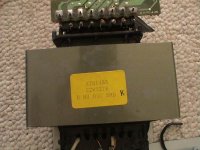
I took apart my Pioneer VSX-402 (and it was a sad thing, too college memories), hoping to re-use some of it. Problem is, all the stuff is integrated, but among a few things, the transformer seems to be salvageable.
I just don't know much about it, and I don't know where to find info for it, and not just the rating, but HOW to salvage it and use it again.
Thanks,
Dave
There was a thread somewhere on this forum about salvaging transformers, but I can't find it.
I took apart my Pioneer VSX-402 (and it was a sad thing, too
college memories), hoping to re-use some of it. Problem is, all the stuff is integrated, but among a few things, the transformer seems to be salvageable.I just don't know much about it, and I don't know where to find info for it, and not just the rating, but HOW to salvage it and use it again.
Thanks,
Dave
Attachments
If you still have the rest of it, you will have better luck. If you can spot where the secondaries connected to the rectifiers you will know where to measure from. If not, you can slap a voltmeter on all the secondaries relative to each other. If some of the outputs don't make sense, you know they probably aren't a proper secondary voltage. Another way is to see with an ohmmeter if the secondaries are all one wire or are they separate windings...
once you have the Tx identified as Stocker suggests, remove the solder and pull the Tx off the board. make sure the keep the parameters with the Tx so you can keep track of it. The bridge from the second pic might also be worth taking.
There's no trick to reusing a Tx, if it has suitable secondary voltages, then put it in there. Since you may not know the VA or current limits [can we assume they are low since this is a commerical product?], I know of no sure way to determine the maximum rated current. Good luck!
There's no trick to reusing a Tx, if it has suitable secondary voltages, then put it in there. Since you may not know the VA or current limits [can we assume they are low since this is a commerical product?], I know of no sure way to determine the maximum rated current. Good luck!
This is what I was afraid of. There was no "rest of it." When I said "integrated," I wasn't kidding; the board pictured was soldered directly to the housing of the transformer, as though the two were manufactured only for each other. No gangly wires were there or anything. It seems the primaries and secondaries are accessed through that board.Evan Shultz said:once you have the Tx identified as Stocker suggests, remove the solder and pull the Tx off the board. make sure the keep the parameters with the Tx so you can keep track of it. The bridge from the second pic might also be worth taking.
There's no trick to reusing a Tx, if it has suitable secondary voltages, then put it in there. Since you may not know the VA or current limits [can we assume they are low since this is a commerical product?], I know of no sure way to determine the maximum rated current. Good luck!
Power rating: 230 watts. I'll do some googling now.
Oh well, I need a nice 20 pound dumbell for exercise.
Thanks,
Dave
Come on now, don't give up so easily!
Measure the secondaries and find out what's what. Solder some wires to the primaries to get them to a mains socket and see what the secondaries give you. Then divide that voltage by 230 for your favorite secondary voltage, and you will have a (probably optimistic) voltage and current rating.
It's easy.
Don't forget a fuse!Stocker said:Solder some wires to the primaries to get them to a mains socket and see what the secondaries give you.
I would probably just connect 12V AC to the primary for more safe measuring...
Best regards,
Mikkel C. Simonsen
Actually, in the first typing I had both a fuse and a GFCI socket. In my own testing I used very fine wire to go to a GFCI power strip. Either way, if the unit was not non-functional because of the power section, the transformer should need nither.
You know, if you just want it to be used and don't care to work at it, you could always ship it to me...
...for the cause, of course!
You know, if you just want it to be used and don't care to work at it, you could always ship it to me...
...for the cause, of course!
Measure the DC resistance of the different windings. There will probably be two windings (or a center-tapped one) with very low resistance. That's the main secondary.
What mains voltage did the amp run on? 120V only, or 100, 120, 220, 240 etc? If it's 120V only, it much easier to find the primary... You will then have a winding with higher resistance than the secondaries. You may also have other windings with even higher resistances, but they may be low-current windings for preamp stages.
When you have found what you think is the 120V primary, connect 12V AC to that. You should then be able to measure the different secondary voltages (/10). But be careful! If what you thought was the primary wasnt, there could be 100-200V at the winding that is...
Best regards,
Mikkel C. Simonsen
I think you're right, but here, take another look from a better angle.
Thanks,
Dave
An externally hosted image should be here but it was not working when we last tested it.
Thanks,
Dave
I am extraordinarily tired so nobody bite my head off if my answer is a little muzzy, please!
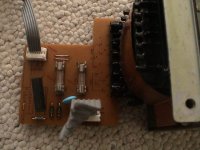
With that picture, I have to revise my previous comment. The secondary is almost 100% going to be the side with the many pins out. The primary is a little different that what I am used to seeing but not unusual per se, if I am correct. The reason for 3 wires on the primary side is so you can use it for 110 or 220... if you want to use 220, you need half as much primary wire to get the same volts out the secondary. Wind on another approximately equal number of turns and you can get the secondary voltages... Split the primary in two (center tap) and you can use it either way, depending on where you are going to sell it. The 2 pins on the primary side look to be on single wires each, and the non-pin wire looks like the connection in the middle. Hook those two pins up and see what you get out all the other ones on the other side of the tranny.
With that picture, I have to revise my previous comment. The secondary is almost 100% going to be the side with the many pins out. The primary is a little different that what I am used to seeing but not unusual per se, if I am correct. The reason for 3 wires on the primary side is so you can use it for 110 or 220... if you want to use 220, you need half as much primary wire to get the same volts out the secondary. Wind on another approximately equal number of turns and you can get the secondary voltages... Split the primary in two (center tap) and you can use it either way, depending on where you are going to sell it. The 2 pins on the primary side look to be on single wires each, and the non-pin wire looks like the connection in the middle. Hook those two pins up and see what you get out all the other ones on the other side of the tranny.
This is something I've been suspecting all along. I think I'll take it to my local electronics supplier and see if he can help me accurately figure it out because the more I think about it, the tireder my brain gets, too.Stocker said:The reason for 3 wires on the primary side is so you can use it for 110 or 220... if you want to use 220, you need half as much primary wire to get the same volts out the secondary.
Dave
Cab you snap a pic (or scan) the foilside of the circuit board and draw in the components on the other side? (is the black rectangle a bridge rectifier?)
I suspect the side with the board is the secondary.
A variac, a voltmeter, paper & pencil, plus some deduction will tell you what you have...
dave
I suspect the side with the board is the secondary.
A variac, a voltmeter, paper & pencil, plus some deduction will tell you what you have...
dave
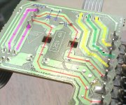
I can, and did. I'm a little confused by the two "AC Mains." The tracings are quite easy to see in the pictures. I couldn't see them with the naked eye.
...and the other side....
An externally hosted image should be here but it was not working when we last tested it.
...and the other side....
An externally hosted image should be here but it was not working when we last tested it.
I can't make them all out, but it is pretty clear what most everything is. Yellow is 110 in (green is ground), red is secondary, purple is recified AC... if that one big fat trace is secondary ground then you have a bipolar supply, if not you have only one rail.
Normally you would connect the output of a variac to the yellow.. If you are VERY careful you can connect 120 V. Then measure the voltage across the red... also between red and the unmarked fat trace between the 2 reds. (if it is secondary ground it will be 1/2 of red-red).
Report back
dave
Normally you would connect the output of a variac to the yellow.. If you are VERY careful you can connect 120 V. Then measure the voltage across the red... also between red and the unmarked fat trace between the 2 reds. (if it is secondary ground it will be 1/2 of red-red).
Report back
dave
Attachments
Banned
Joined 2002
kneadle said:I think you're right, but here, take another look from a better angle.
An externally hosted image should be here but it was not working when we last tested it.
Thanks,
Dave
have yo figured this out ? If not let me know i know the answer..
little hunt Thermal / Protection fuse on the main of that tranny : O ) ill draw it on the pic of you still need to figure out witch side is ac in
Jason
I am making progress, with a great step toward figuring it out with that tracing by dave (planet 10). First, I need to work up the courage to hook voltage up to this mama. Passive electronics is one thing, but adding amps and volts to a circuit proves me to be a newbie. Would someone like to suggest a safe way to get 120V to this naked Tx?
Is that what a variac is for?
Thanks,
Dave
Is that what a variac is for?
Thanks,
Dave
- Status
- This old topic is closed. If you want to reopen this topic, contact a moderator using the "Report Post" button.
- Home
- Amplifiers
- Chip Amps
- Salvaging Transformers