Hoffmeyer said:Hi digi01.
Interesting design.
I found some time ago some interesting designnotes at UltraCAD , on the subject "Maintaining clean power".
If You cheat a little in the addressline, You can find 9 tech-notes, many of interest")
thank you.
yes,I think it is interesting.
You can use this part to hook up a stereo GC,make it work in bridge. or drive a balanced input power amp.

 Look good!
Thanks for your reaction.
What i mean is: were do you use a balanced line driver for? What is it? What can you do with it? does it come in place of a pre-amp, or can you use it in combination with a pre-amp and a power amp?
When i know what is is for, i want to use it for audio, for gainclones (i have build several, and they sound great).
Sorry for my silly questions.
Hi wim-
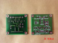
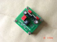
Well the purpose digi01 built it for is to build a bridged gainclone.
This circuit (using the EXCELLENT drv135 chip) is taking a NON-inverting signal and splitting it evenly to send out a balanced + and - signal to drive the inputs of matching (hopefully paralleled) Gainclones.
Therefore one gainclone amplifies the positive half of the signal, and the other Gainclone amplifies the negative half of the signal.
When the two halves are combined the amplifier develops "roughly" twice the voltage swing and power output.
If the gain of the drv135 can be raised above 1 then it could be used as the pre-amp in the front end of a controller or high gain amplifier.
- Home
- Amplifiers
- Chip Amps
- Balanced line driver, PCB layout share