AndrewT said:
is this AC output a combination of noise and/or hum?
Have you listened to it.
an ordinary speaker will reveal much about it.
A pair of headphones will reveal it at very loud level.
i think there's no problem, if the output voltage of my cdp layer is 2v and the bridge adapter has 10mv output that means an attenuation of 200. i have measure the output voltage in my passive preamplifier ( 100 k), and the attenuation is much lower, from 2v in the cd output to 80mv in the passive pre output. I think it can't be audible.
for those interested in make bridge driver with universal opamps,i have a completed design last year.
here is the device photos,sch,bom:
http://www.diyaudio.com/forums/showthread.php?s=&threadid=118894
http://assemblycraft.com/bridge_preamp.html
-Zang
here is the device photos,sch,bom:
http://www.diyaudio.com/forums/showthread.php?s=&threadid=118894
http://assemblycraft.com/bridge_preamp.html
-Zang
juluska said:
i think there's no problem, if the output voltage of my cdp layer is 2v and the bridge adapter has 10mv output that means an attenuation of 200. i have measure the output voltage in my passive preamplifier ( 100 k), and the attenuation is much lower, from 2v in the cd output to 80mv in the passive pre output. I think it can't be audible.
i guess your passive preamplifier (100k) without decoupling caps in the signal route.
digi01 said:for those interested in make bridge driver with universal opamps,i have a completed design last year.
here is the device photos,sch,bom:
http://www.diyaudio.com/forums/showthread.php?s=&threadid=118894
http://assemblycraft.com/bridge_preamp.html
-Zang
nice work. What is the price for a complete stereo kit with components?
thanks
I thought I'd try the Jaycar KC5469 bridging kit just to see if it was any good.
It was extremely easy to build with all hole-through components widely spaced (too widely spaced, PCB is a bit big). It seems to work fine though. It comes with a LM833 opamp. Also, there is an option on the PCB for using the amps PSU to power it with 2 x 15v 1W zeners and 4x 1W resistors, that are a different value depending of the voltage of the amps PSU.
One drawback is that it only has a mono input. I would like to use it to power a sub. So I need to sum a stereo pair and use some kind of low pass to filter it down to 200hz before the input. Is it possible to use a PLLXO type filter with this?
col.
col said:Will your boards run on 15v?
the board supply with +/-18VDC to +/-30VDC,it have fixed regulator chips LM78L15,LM79L15.
here is the sch&bom:
http://assemblycraft.com/0903img/bridge-v1.1.GIF
all the best,
Zang
digi01 bridge adapter
I've just finished my first bridging adapter for the bpa300 following the digi01 schematic in a quad opamp. It works really good, see here the results.
http://ignatiusprojects.blogspot.com/
In the next board i will mount the regulated PSU and adapter in the same board.
BPA300 amplifier sounds superb.
Thanks to all.")
I've just finished my first bridging adapter for the bpa300 following the digi01 schematic in a quad opamp. It works really good, see here the results.
http://ignatiusprojects.blogspot.com/
In the next board i will mount the regulated PSU and adapter in the same board.
BPA300 amplifier sounds superb.
Thanks to all.
hello digi01, hope its not to late to post here.
I wonder (as i am very new to this) why does your pcb have a positive and a negative voltage regulator? All the circuits i have experimented with recently have just used a positive regulator. Will this drv134 chip only work with a + and - regulator connected to pins 5 and 6?
thanks for any info : )
I wonder (as i am very new to this) why does your pcb have a positive and a negative voltage regulator? All the circuits i have experimented with recently have just used a positive regulator. Will this drv134 chip only work with a + and - regulator connected to pins 5 and 6?
thanks for any info : )
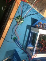
Hey! Don't know if anybody is still monitoring this... I'm trying to get in touch with Digi01 (Zang) I bought a bunch of his balanced line driver PCBs and finally got around to building. I'm having some weird issues. Everything seems to be correct with the build but I'm getting a pulsed noise and the 18 volt input is dropping to 0 and pulsing up to 6 volts or so when the circuit is connected.
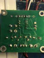
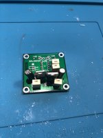
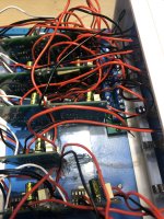
Great! OK I've got 10 units built and installed but they all do the same thing, singly or together. Pulsing from 0 to 4-6 volts when metered from ground to outputs. The power supply is 18 v DC center positive. I'm powering them all from a small rail. I've got one isolated for testing. Show in pics: Original layout from Digi01 circa 2006, Back of one of mine, Top of one of mine, The loaded chassis, The test set up and the schematic. Any help much appreciated!
Attachments
Last edited:
Yes! It's been a while. These PCBs have been sitting on my shelf for 10 years! I think I got it worked out. The circuit requires BOTH neg and pos power. I have no instructions and I though the - and+ markings on the power input were to identify which side of the system they powered as it has a positive side and a neg side, so I was putting +18 on both sides. Got a converter that supplies both and that did the trick!
I don't have it all assembled yet but tests look good. I'm going to use this to fix the direct, unbalanced channel outs from a vintage Allen+Heath mix console going into a modern digital converter. Been using it unbalanced forever and figured I'd see if this makes a difference.
- Home
- Amplifiers
- Chip Amps
- Balanced line driver, PCB layout share