Ok ive got my bridges using MUR860 diodes built onto Vero board (The board with the strips). Now the power supply is fine under no load and measures approx 37 volts on each rail.
But once connected to the circuit the strip which connects two diodes and a cap and becomes the ground burns off the board literally.
Is this the circuit drawing too much current for the board or is there something else wrong?
Will get a schematic up tomorrow morning.
Thanks for your time,
Joel
But once connected to the circuit the strip which connects two diodes and a cap and becomes the ground burns off the board literally.
Is this the circuit drawing too much current for the board or is there something else wrong?
Will get a schematic up tomorrow morning.
Thanks for your time,
Joel
ive done some on strip board aswell and all fine if a little warm!!
try leaving the legs long, bending them along the strip board and soldering all the way along, similar to point to point. that can help with heavy current loading.
and im talking 15 amps, 40 volts. so it can be done. IF, your circuit is correct.
hope this helps, see you soon, steve.. ..
try leaving the legs long, bending them along the strip board and soldering all the way along, similar to point to point. that can help with heavy current loading.
and im talking 15 amps, 40 volts. so it can be done. IF, your circuit is correct.
hope this helps, see you soon, steve.. ..

OK ill work on that now. But another question about the windings. The dot on the schematic denotes the start of the winding but does it matter what part of the bridge it is connected to?
Like does it matter if A and B where swapped around?
Sorry for my n00b questions but transformers are new for me.
Like does it matter if A and B where swapped around?
Sorry for my n00b questions but transformers are new for me.
I can't see it well enough on your copy, but looking at the power supply drawing I think that for the lower rectifier section the + and - might be swapped.
In other words: The + out of the second/lower rectifier section should be connected to ground of the first bridge and the make the GND for the amp.
The negative output of the second rectifier section should be connected to -V
Also you should make sure that A and B are indeed not swapped. This can be verified when powering up without the rectifiers, connect B and C and measure the voltage between A and D. It should be double so around 44 Volts.
regards,
Maarten
A rectifier bridge has two input points and two output.
On a ready-built bridge, the (AC) input points will probably be marked with the AC symbol liked this ~
The (DC) outputs will be marked + and -
On a discrete bridge, you need to understand the corresponding points. If you look at my
GC FAQ page you can see this diagram which will enable you to identify the correct connection points.
Also look a the picture on the FAQ page just below that diagram. You can see the red and black DC connecting wires. The AC wires from the transformer go between the two pairs of diodes.")
On a ready-built bridge, the (AC) input points will probably be marked with the AC symbol liked this ~
The (DC) outputs will be marked + and -
On a discrete bridge, you need to understand the corresponding points. If you look at my
GC FAQ page you can see this diagram which will enable you to identify the correct connection points.
An externally hosted image should be here but it was not working when we last tested it.
Also look a the picture on the FAQ page just below that diagram. You can see the red and black DC connecting wires. The AC wires from the transformer go between the two pairs of diodes.
Hi Scribble
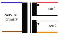
one question, does your transformer have 4 wires on the primary or 2?
if i am guessing correctly, it is 2, which means you are shorting out the transformer when you are applying a load! eek!
you cannot use that transformer/bridge setup if you are using a locally available transformer of which all are single 240V primaries.
where did you get your transformer from?
So this is my PSU that supplies two channels. Each channel takes a - and + from each bridge. The -'s meet up to form the star ground and the -v and +v go to there respective pins.
Upon measurment both rails give about 37volts under no load but once connnected to the circuit KA-BLAMMO!
There goes the strip that connects the -v, ground connections (ie: cap and two anodes)

Upon measurment both rails give about 37volts under no load but once connnected to the circuit KA-BLAMMO!
There goes the strip that connects the -v, ground connections (ie: cap and two anodes)
So if the Dot line goes to one point and the non-dotted line goes to the other point, how do you determine which ~ part of the bridge each wire goes on?
I see there is a dot on the schematic put because the bridge is symetrical it doesnt make sence to me when the bridge is constructed
I see there is a dot on the schematic put because the bridge is symetrical it doesnt make sence to me when the bridge is constructed
Scribble said:So this is my PSU that supplies two channels. Each channel takes a - and + from each bridge. The -'s meet up to form the star ground and the -v and +v go to there respective pins.
Upon measurment both rails give about 37volts under no load but once connnected to the circuit KA-BLAMMO!
There goes the strip that connects the -v, ground connections (ie: cap and two anodes)
Please show us how you have the '+' and '-' of each bridge connected to the rest of the circuit and each other.
Hi Scribble
first things first, do u have a fuse on the primary? most important, i believe it should have blown by now.
if i have the colours right, you have to join black & white to form the GND. red is therefore one secondary and orange your second.
this is secondary in series.
this will give you 25 + 25 VAC with 10A capability.
if you want more amps you can wire red to white and black to orange to get secondary in parrallel.
this will give you 25 + 25 VAC with 20A capability.
the dots denote the starts of the wiring. it should be on the side of the transformer or in the catalogue.
personally, i would go the first option. secondary in series, and use only one bridge. easy.
the reason the transformer is working in that black and white schematic you posted is because it has a very different winding scheme. enabling the use of 2 bridges on that secondary winding setup.
Attachments
His schematic is using dual bridges so you dont want to join the 2 secondary windings prior to the bridges.phs said:if i have the colours right, you have to join black & white to form the GND. red is therefore one secondary and orange your second.
this is secondary in series.
this will give you 25 + 25 VAC with 10A capability.
Incorrect. It would give 25 VAC with 20A capability.phs said:if you want more amps you can wire red to white and black to orange to get secondary in parrallel.
this will give you 25 + 25 VAC with 20A capability.
Using 2 bridges as per his schematic is the perferred method and has a few benefits over a single bridge.phs said:personally, i would go the first option. secondary in series, and use only one bridge. easy.
apart from the primary, his transformer is fine. Given that he seems to have wired the primary correctly, the rest of the circuit should be fine as per his schematic.phs said:the reason the transformer is working in that black and white schematic you posted is because it has a very different winding scheme. enabling the use of 2 bridges on that secondary winding setup.
I still would like to see how the two secondary sections are joined together, since I think the first schema might contain an error.
This is (in different way of drawing) the schema I use, should be the same for you too.
The PG- and PG+ are connected to form the Power Ground for the amplifier.
Maarten
This is (in different way of drawing) the schema I use, should be the same for you too.
An externally hosted image should be here but it was not working when we last tested it.
The PG- and PG+ are connected to form the Power Ground for the amplifier.
Maarten
Nuuk,
Look again at the first schema posted by Scribble. The positive output of the second rectifier bridge is connected to -V of the amp and the negative output of the rectifier bridge is connected to ground (which is taken together by the ground of the first bridge).
This is not correct ... negative output of second bridge must be the -V point for the amp and the positive side should be connected to power ground.
And if soldered that way on the board all strange things can happen especially if the AC wires of the secondaries are switched.
Maarten
Nuuk said:Just a thought guys! The problem wouldn't be with using a non-polarised cap across the bridge would it?
It would be worth trying a polarised type after the bridge!
No, and that's how Brian ships 'em
Maarten
Ok i will try and get some pics of my psu for you guys tomorrow.
Still quite havnt got my head around the secondary winding polarity buisness yet but im trying. I am positive that i have AC going in to the AC section as i get a voltage on both rails.
So do you think the schematic is wrong and that i should swith the -v, + and - points? ie, current +-V should be join'd to the star ground and the current ground attached to the chip's +-v input?
Thanks for all your help guys,
Joel
Scribble,
With all the + and - signs it's getting confusing a little bit, so let met me add some text to the schema above. In principle it's all there.
The power supply for the gainclone is made of two separate rectifier sections that are joined in series so that there is a V- , GND and a V+ connection for the chip.
V+ is the positive output of first bridge, PG+ is the negative output of first bridge. It will be connected with the positive output of the second rectifier section (PG- in my picture). Together they make the GND reference for the amp.
V- is the negative output of the second rectifier and therefore the negative rails.
You can check with a meter: Between V+ and PG+ it must read about 36 volts, Between PG- and V- must read about 36 Volts and when taking PG+ and PG- together there must be around 72 volts between V+ and V-. (Actual voltages may be higher without load)
regards,
Maarten
- Status
- This old topic is closed. If you want to reopen this topic, contact a moderator using the "Report Post" button.
- Home
- Amplifiers
- Chip Amps
- Vero board under load