hi,
Im sure this has been mentioned quite a few times, but i did a quick serch and didnt find to much of revelance.
I have a HT set up but need a decnt sub and amp, the amp and creading the box and so forth are of no real issue, but i cant seem to find a cheap off the shelf sub amp, in australia.
I was wondering if there wa any good DIY amps that i could use for this. I only plan to use one sub 10 or 12 inch, and my amplifier has a sub out socket.
I can solder circuit borads and do a bit but dont know too much thus i like the Gainclone design, could a gainclone design amp be used, also why have i not seen any specs for the output for a gainclone, everone seems to be building them but i have not seen any power ratings (have i just missed them).
thanks for youre help,
PS if their is a thread that has covered this already please let me know so i can save everone time.
jonesy
I am working on this, the board layout is complete, and I am hoping to etch and assemble the board today and see how it comes out.
It uses 2 3875 chips bridged. The chips both run in non-inverted mode, but a DRV134 chip inverts one amp and not the other.
Finally, there is a crossover using the LM833 Audio OPAMP. The crossover gain and frequency is adjustable.
http://www.diyaudio.com/forums/showthread.php?s=&threadid=41005
It uses 2 3875 chips bridged. The chips both run in non-inverted mode, but a DRV134 chip inverts one amp and not the other.
Finally, there is a crossover using the LM833 Audio OPAMP. The crossover gain and frequency is adjustable.
http://www.diyaudio.com/forums/showthread.php?s=&threadid=41005
Here is some good reading
http://www.national.com/an/AN/AN-1192.pdf#page=1
I'm looking at making a 100W Parallel Circuit later for a sub that will go with some tangbands.
Hope this helps
Jye
http://www.national.com/an/AN/AN-1192.pdf#page=1
I'm looking at making a 100W Parallel Circuit later for a sub that will go with some tangbands.
Hope this helps
Jye
soundNERD said:The chips both run in non-inverted mode, but a DRV134 chip inverts one amp and not the other.
Are you using both outputs of the DRV134 or just the inverting one? On the latter case it would be a waste to use that chip.
Carlos
Yes, I am, otherwise, like you said, its a waste.
I have both amps in NI mode with the inverting output going to one amp and the non inverting going to the other chip.
If you do not have one of those, you could probably rig a dual opamp into there if the pins are right and invert one, or try and mess with the amps to make one invert.
I have both amps in NI mode with the inverting output going to one amp and the non inverting going to the other chip.
If you do not have one of those, you could probably rig a dual opamp into there if the pins are right and invert one, or try and mess with the amps to make one invert.
soundNERD said:Yes, I am, otherwise, like you said, its a waste.
I have both amps in NI mode with the inverting output going to one amp and the non inverting going to the other chip.
If you do not have one of those, you could probably rig a dual opamp into there if the pins are right and invert one, or try and mess with the amps to make one invert.
If you are doing like you said, it's not a waste: it's as how it should be. Inverting output to one amp, non-inverting output to the other. That's what bridging is.
The fact that you are using a NI mode on the amps is also right and it's what I would do.
The advantage of using the DRV134 is that you do the bridging with more precision than when using two singles or a dual op-amp. Very much like what you would do with a transformer.
Carlos
yep
exactly why i did that.
Hopfully it will make a difference with a sub.
While were talking about the 3875, does it work ok with a 4ohm? according to the graph on the datasheet, it can't do 4ohm. Is this true? If so I guess I'm going with a 3886.
One more question, how would a bridged 541 be for a sub? I want to use a 549, but my PS is too high voltage for it. Would I get more power bridging a 541 into a 8ohm sub than a 3886?
thanks!
If I remember correctly (I've read this a few times here and elsewhere):
The 3875 wants less input voltage to handle 4ohms IIRC. 18VA trafo is usually recommended, though 22V is a good balance between 4ohm and 8ohm performance.
In this case, the 3886 does seem better suited to the application, particularly if you ever find yourself with a 4ohm driver.
C
The 3875 wants less input voltage to handle 4ohms IIRC. 18VA trafo is usually recommended, though 22V is a good balance between 4ohm and 8ohm performance.
In this case, the 3886 does seem better suited to the application, particularly if you ever find yourself with a 4ohm driver.
C

Sorry, I have no schematics,
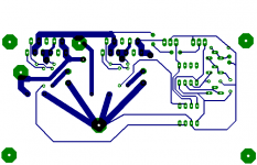
It's just two OPA541 amps using the circuit for the lm3875 in Non inverting mode (I originally was going to use the 3875, but after learning it can't drive an 8-ohm speaker in bridged mode, I decided against it, so changed the board for a 541). The crossover is a standard LM833 Audio OPAMP with adj. gain and frequency. It's a 2nd order lowpass filter. Finally, the DRV134 Circuit is just pins 1 and 2 driving one amp and 7 and 8 driving another amp, then power, input and ground. Power is suppled to the chips with a LM7812 and 7912 regulator. You can use anything from a 7805/7905 to a 7815/7915 regulator. The higher the better.
The amp can run off of up to a +/-40 supply, but I'd stay below that since thats the absolute max rating on the chip.
Heres the eagle file for the board:
Attachments
Sidd
Most members read every thread in their area of interest, so you don't really need to cross post so much. One thread at a time will do.
I'm sure also the info you're asking for has already been posted. Did you search? Sometimes if you search and you get lots of info, you can narrow it down ticking the box on the search page that shows the posts only, not the entire thread.
It's hard to generate a JPEG file at the right size and also with a high quality image. They usually come out too large and when scaled down lose image quality.
Also, I would go for an OPA549, because I gave up on the 541 after it started on fire twice. I've never had a single problem with a 549, and it even puts out more current.
To view the file, download eagle from www.cadsoft.de and print it from there.
Also, I would go for an OPA549, because I gave up on the 541 after it started on fire twice. I've never had a single problem with a 549, and it even puts out more current.
To view the file, download eagle from www.cadsoft.de and print it from there.
hey i have downloaded the eagle software.
ok so the file that u have sent (sub_amp) it is the layout of a opa549 right?
so could u send me the schematics cuz i cant understand where the input is and where the output is and all that. ( i know i must be sounding stupid, but hey u were an amatuer too right?)
and also send me any substitutes possible 4 those lm ics.
and i have a 20-0-20v 5amp transformer will that run this amp?
- Status
- This old topic is closed. If you want to reopen this topic, contact a moderator using the "Report Post" button.
- Home
- Amplifiers
- Chip Amps
- DIY Sub amp recomendations??