I have put together my BrianGT Gainclone and I am currently testing it and have 42mV of DC offset in one channel and 80mV in the other.
About my setup:
I have connected AC ground to both PCBs CHG.
It is on a desk, not in a case.
Input is the short redish fat cable that is not connected to anything because I see that Input Ground is connected to CHG on the PCB anyway.
I am using a 10 Ohm resistor to measure the DC offset.
I am very sure all my soldering is good and suspect I have mis read something about grounding?
I have read all the grounding posts I could find and the NIGC userguide and this http://www.decdun.fsnet.co.uk/gaincloneFAQ.html page.
Here is a pic of my setup:
Some one tell me what I have done wrong
About my setup:
I have connected AC ground to both PCBs CHG.
It is on a desk, not in a case.
Input is the short redish fat cable that is not connected to anything because I see that Input Ground is connected to CHG on the PCB anyway.
I am using a 10 Ohm resistor to measure the DC offset.
I am very sure all my soldering is good and suspect I have mis read something about grounding?
I have read all the grounding posts I could find and the NIGC userguide and this http://www.decdun.fsnet.co.uk/gaincloneFAQ.html page.
Here is a pic of my setup:
An externally hosted image should be here but it was not working when we last tested it.
Some one tell me what I have done wrong
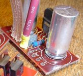
First picture: I cannot see a ground connection between the rectifierboard and the central ground. Missing? Or is there no ground at Brians rectifier boards, just diodes on it?
Question: the blue cables are the ground? They are to long, as here is current flowing! Suggestion: You better use a very thick and short blank cupperwire between the two boards. In the middle of this wire you can connect the PSU and the AC ground.
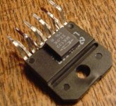
Second picture: between wich pins did you connect the feedback resistor?
Franz
Question: the blue cables are the ground? They are to long, as here is current flowing! Suggestion: You better use a very thick and short blank cupperwire between the two boards. In the middle of this wire you can connect the PSU and the AC ground.
Second picture: between wich pins did you connect the feedback resistor?
Franz
Franz G said:First picture: I cannot see a ground connection between the rectifierboard and the central ground. Missing?
I didn't know you needed one! I cant see one in the pics in the userguide. What connection does it come from?
Franz G said:Question: the blue cables are the ground? They are to long, as here is current flowing! Suggestion: You better use a very thick and short blank cupperwire between the two boards. In the middle of this wire you can connect the PSU and the AC ground.
[/B]
The blue cables are CHG. So connect both CHGs and then one cable from this to star ground which also has the chassis (not yet though) and AC ground connected to it?
Franz G said:Second picture: between wich pins did you connect the feedback resistor?
Franz [/B]
pin 3 and 8, see attached pic.
Thanks alot for your time
")
Attachments
Sorry, when I am confusing you, about the rectifier board, as I edited my posting to late.
There is no ground at brians rectifier board, of course.
Yes, this is a way to go. The middle of the "new" connection should be the "star center".
Franz
There is no ground at brians rectifier board, of course.
The blue cables are CHG. So connect both CHGs and then one cable from this to star ground which also has the chassis (not yet though) and AC ground connected to it?
Yes, this is a way to go. The middle of the "new" connection should be the "star center".
Franz
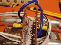
Franz G said:When I look again your first picture: Just shorten the blue cables as much as possible, connect them and try...
Franz
Done and its the same (see attachment pic)
Would this rule out a grounding problem?
Attachments
Franz G said:Oops, now you do have a small ground loop! Sorry, I was misleading again.
Remove the (thin) cupper wire between the boards, as the blue cables are doing the job.
Franz
Done and still the same offset

Thanks for your patience
Franz G said:Max
Wait, till our US friends wake up! I leave now, to drink my breakfast coffee!
Franz
Thank for your help and enjoy your day
I don't think this is anything else than what you can expect and nothing really to worry about.
Some examples of the chips do have higher offsets than others.
And this is what I wrote after building an NIGC circuit.
Full story of that NIGC is
here .
For the record, that amp was sold to a friend and has run without any problems for nine months now. My friend who is a musician is very impressed with the sound quality!
Some examples of the chips do have higher offsets than others.
And this is what I wrote after building an NIGC circuit.
With the damaged capacitor replaced, I powered up again and measured the DC offset on each channel. One channel measure 90mV and the other 75mV. I decided that this was a bit high and changed the 680 ohm resistor to ground with a 1K. This brought the offsets down to 55mV and 40mV which I am more happy with.
Full story of that NIGC is
here .
For the record, that amp was sold to a friend and has run without any problems for nine months now. My friend who is a musician is very impressed with the sound quality!
DC offset ( and drifting of this ) can be " kill " only by DC servo. By the way, oncetime I had read test of one here well known machine, where author says : " By switch on is DC offset app. 150 mV, but after five hours fall on phantastic value 50 mV " . As we see, looking at DC offset is realy relative.
As we see, looking at DC offset is realy relative. Upupa Epops said:DC offset ( and drifting of this ) can be " kill " only by DC servo. By the way, oncetime I had read test of one here well known machine, where author says : " By switch on is DC offset app. 150 mV, but after five hours fall on phantastic value 50 mV " .
so you think my offset readings are fine? or do you mean that as long as they are the same on both channels it doesn't matter?Hi Max,
These posts may help clear it up for you. I am experiencing up to 120mV offset and not particularly bothered
If it bothers you than you can adjust the resistance from signal in to ground, or perhaps try the Ci cap as shown on the National schematic.
Also once you have a pot in place, you will find the offset will go down too.
Vikash said:Hi Max,
These posts may help clear it up for you. I am experiencing up to 120mV offset and not particularly bothered
If it bothers you than you can adjust the resistance from signal in to ground, or perhaps try the Ci cap as shown on the National schematic.
Also once you have a pot in place, you will find the offset will go down too.
Thanks Vikash. I see peter said to make a PCB up and just place the IC in and test it. I did that and measured the other 2 chips I had and one was 60mV and the other was 175mV. I did each one twice to make sure and the measurements were the same.
- Status
- This old topic is closed. If you want to reopen this topic, contact a moderator using the "Report Post" button.
- Home
- Amplifiers
- Chip Amps
- DC offset problem