Hi all!
I have a problem with my gainclone using the 4780.
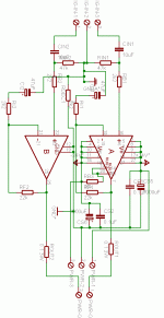
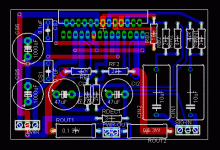
Rails are at +-20V, you can find the schematic on the attached images.
Each aml is driven by a balanced input so that schemetic become a bridged version, despite the NI port used for both opamps.
The problem is that I got DC on the exit, and I can't find why.
The strange thing is that I've tested some circuit before to be placed in their case and they behave as expected...
Do you have any hint on how troubleshoot the problem?
Attachments
one reason is becuase you don't have matched input bias currents (or it is unlikely). the DC resistance fron NI to ground is 47k, while the DC resistance from II to ground is 22k.
how much DC are we talking about?
if it is signifigant eg more then 100mV, then i'd say double and triple check all ground and mute connections on the IC. if the mute is wrong or the ground is unsoldered, well, this can happen.
also, is it possible the IC isn't isolated from the heatsink, or the heatsink isn't isolated from the chassie or ect...
theChris said:one reason is becuase you don't have matched input bias currents (or it is unlikely). the DC resistance fron NI to ground is 47k, while the DC resistance from II to ground is 22k.
Oh, this is a mismatch, in reality the 47k is a 22k, so I think this is not a problem.
theChris said:how much DC are we talking about?
if it is signifigant eg more then 100mV, then i'd say double and triple check all ground and mute connections on the IC. if the mute is wrong or the ground is unsoldered, well, this can happen.
It depends on the board, some of them have a 0.6 - 0.8V
theChris said:also, is it possible the IC isn't isolated from the heatsink, or the heatsink isn't isolated from the chassie or ect...
mmmh, I've checked the isolation of the heatsink and seems to be ok (no neg voltage on the chassis) but I will re-check all the solderings on the chip.
I will recheck also the voltage drop across the mute resistor so to be sure that it's working well.
Thank you very much!
thats probably not it. if one IC ground pin isn't connected, then you can get a supply voltage on the output of one IC. i did this once. one channel was putting out 30V and the other worked fine...
for 0.6V i would normally say check the input or the amp internals, but in this case it looks like both are taken care of. can you mute the IC? if so, does the voltage on output change any?
for 0.6V i would normally say check the input or the amp internals, but in this case it looks like both are taken care of. can you mute the IC? if so, does the voltage on output change any?
Thank you Chris,
In fact on one of the 10 amp I'm working on, i have 18.5 V on both outputs... You say it's because of the unconnected GND pin, that' really strange, I've triple checked all the solderings, I'll recheck or re-do all the IC solderings anyway.
I will also try to mute the amp and look what happens.
Another question, may you tell me what happens if the IC is not isolated from the heatsink? Why is it wrong if the heatsink is not connected to anything?
Thank you very much for your support.
Bye,
heatsink not isolated can lead to odd problems. like if you attach the case to ground, the case to the heatsink, and then the heatsink to the unisolated chip... in this case there is a short.
a voltage offset of 18V would indicate to me:
1.) the muting circuit is faulty. confirm that it is soldered at the IC and goes bad to ground somewhere.
2.) DC offset of source. in your case the cap should take care of this. unless you are not using a split supply (like +-20V)
3.) improper feedback. either no feedback or positive feedback. possibly a cold solder joint?
4.) damaged IC. again, this one seems unlikely.
Hi TheChris!
Let me understand. You say that to have 18V (not 20 as your experience) means that the IC is not properly connected (i.e. cold soldering to GND)? Wow, I can't understand how you reach this conclusion, but it's great! I have resoldered all the IC pins to be sure to have a good soldering, but I will redo them.
Infact, I'm quite sure to be out of this problem. I have the caps on the inputs and I'm using the split supply...
Who can say? It may be a cold solder, as stated before I will redo all the solderings, I will also change the tin. This is challenging me, I've made dozen of GC with the LM3886 without any problem, with any design and never, never had a problem with the solderings. This is the first time I use the LM4780 on a PCB, but it's really strange that I have so many problems with good connections...
Wow! I hope not, I had so many samples from National without problems, this IC were regularly bought from National, I can't believe that I have some faulted ones on 15...
Anyway, thank you very much. I will update the status on monday, when I'll have access to my amps again.
Have a nice Week end
theChris said:a voltage offset of 18V would indicate to me:
1.) the muting circuit is faulty. confirm that it is soldered at the IC and goes bad to ground somewhere.
[/B]
Let me understand. You say that to have 18V (not 20 as your experience) means that the IC is not properly connected (i.e. cold soldering to GND)? Wow, I can't understand how you reach this conclusion, but it's great! I have resoldered all the IC pins to be sure to have a good soldering, but I will redo them.
theChris said:2.) DC offset of source. in your case the cap should take care of this. unless you are not using a split supply (like +-20V)
[/B]
Infact, I'm quite sure to be out of this problem. I have the caps on the inputs and I'm using the split supply...
theChris said:3.) improper feedback. either no feedback or positive feedback. possibly a cold solder joint?[/B]
Who can say? It may be a cold solder, as stated before I will redo all the solderings, I will also change the tin. This is challenging me, I've made dozen of GC with the LM3886 without any problem, with any design and never, never had a problem with the solderings. This is the first time I use the LM4780 on a PCB, but it's really strange that I have so many problems with good connections...
theChris said:4.) damaged IC. again, this one seems unlikely. [/B]
Wow!
 I hope not, I had so many samples from National without problems, this IC were regularly bought from National, I can't believe that I have some faulted ones on 15...
 Anyway, thank you very much. I will update the status on monday, when I'll have access to my amps again.
Have a nice Week end
Update
Hi, I've just finished working on the amps.
actually 5 of the amps seems to work well (not already attached to the scope) in static conditions.
The remaining one have a strange behaviour. some times it has 18 V DCC on the out, actually on one channel only, sometimes it has not....
Probably is a cold soldering, but I have re soldered all the components on the PCB, so I'm wondering to know where the fault is.
The mute circuitry is working well, in fact if I disconnect the mute resistor the DCC goes away.
Bye!
- Status
- This old topic is closed. If you want to reopen this topic, contact a moderator using the "Report Post" button.
- Home
- Amplifiers
- Chip Amps
- LM4780 problem

