3 days on EAGLE..this is what i cooked up.
I couldnt locate all required footprints and yet to explore how to create custom footprints.
OK, the pcb is for a single half of LM338 based regulator for LM3886, includes multiple input transistors in the ratio 1x .1x .01x, Power on delay, and provision for SMD tantalum output transitors for improving power supply impedence figures.
ajju
Attachments
Hi Ajju,
I'm very interested in working out a schematic and a board for the LM338 as a regulator in a GC supply. Actually I'm planning to integrate both the PSU and the GC on a single board with SMT components (to keep it tiny).
Creating custom parts in eagles library editor is actually easy and should be done in the first place - my experience. I haven't sorted all the parts out yet, because your board view makes this rather difficult.
Would you like to share your schematic with us (either as a picture and/or as the .sch and .brd file)?
thx,
Sebastian.
 please excuse that momentary lapse of reason...
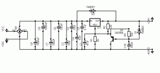
Don't forget the usual high freq 0.1uF decoupling cap at the regulator output.
Try to place the small value caps nearer to the regulator terminals.
If you must use solid tantalum caps, be sure to derate them to 50% of rated voltage. Solid tants have a nasty habit of blowing up. I've seen that happen too many times. Polymer tants are much better.
Good luck.
Try to place the small value caps nearer to the regulator terminals.
If you must use solid tantalum caps, be sure to derate them to 50% of rated voltage. Solid tants have a nasty habit of blowing up. I've seen that happen too many times. Polymer tants are much better.
Good luck.
Very few notes:
1) Put a (at least (and beside high freq decoupling)) 1000uF capacitor at the output of the LM338 - but very close to LM3886 (see LM3886 National application note)
2) The 47uF capacitor at the adj pin is unusefull beause of 100uF at the base of Q1 (the equivalent capacitor at the adj pin is 100uF * gain of Q1). In any case if you keep the 47uF capacitor put a diode in the same manner as D1 at the adj pin.
3) To get a 24 V DC output voltage you need (at least) a 24 V AC transformer (if you need detailed calculation, ask).
If you let a +10% fluctation of mains voltage you get
24*sqrt(2)*1.1=37 V peak at the input of the regulator, near the 40V rating of the regulator. Be aware of the no load - full load regulation of the transformer!
4) Put a reverse (anode to ground) diode at the output
5) What about the negative regulator?
Regards
diy_audio_fo said:Very few notes:
1) Put a (at least (and beside high freq decoupling)) 1000uF capacitor at the output of the LM338 - but very close to LM3886 (see LM3886 National application note)
The idea was to use this as a dedicated power supply board. The LM3886 will sit on another PCB and so will the 1000uf Caps.
2) The 47uF capacitor at the adj pin is unusefull beause of 100uF at the base of Q1 (the equivalent capacitor at the adj pin is 100uF * gain of Q1). In any case if you keep the 47uF capacitor put a diode in the same manner as D1 at the adj pin.
Yes, you are correct. A diode is indeed essential to allow a fast discharge path for C1 . I missed that in the schematics.
Q1 does not operate in the active region at all times. Only on power on Q1 has a role. During power on Q1 will conduct for a time approx. determined by rise time of R3 C10. Q1 eventually gets cut off. (Q1 also might have a role to play following recovery from an output short or a very heavy load.)
The 47uf has been added and is essential to reduce ripple and noise effects.
3) To get a 24 V DC output voltage you need (at least) a 24 V AC transformer (if you need detailed calculation, ask).
If you let a +10% fluctation of mains voltage you get
24*sqrt(2)*1.1=37 V peak at the input of the regulator, near the 40V rating of the regulator. Be aware of the no load - full load regulation of the transformer!
asking...!
")
I thought i can settle for a 22V or 20V transformer, with some tradeoff in ripple at heavy loads.
4) Put a reverse (anode to ground) diode at the output
Why is this reqiured...? is it to protect from inductive spikes..?
5) What about the negative regulator?
Negative regulator will be the same..
The transformer will have a split secondary and each secondary will have its own regulator. After the regulator, at the output the GND and +24V out of the two seperate regulators will be tied to gether to form the ground, and to get the dual supply.
However for this its a must tha we use a transformer with a split secondary.
-ajju
> Q1 does not operate in the active region at all times. Only on power on Q1 has a role.
>The 47uf has been added and is essential to reduce ripple and noise effects.
Good points. I missed them.
>asking...!
>I thought i can settle for a 22V or 20V transformer, with some tradeoff in ripple at heavy loads.
Vout= Output voltage
Vin-out = minimum differential input-output voltage for regulator
Vr=Vripple
2Vd= Voltage drop on the bridge
Vpeak_sec= Transformer peak secondary voltage
Vsec= Transformer RMS secondary volatge
Let's say:
Vout=24V
Vin-out = 3V
Vr =10% *(Vout + Vin-out)= 2.7V; 10% is a "rule of thumb" number choosen not to stress the transformer with high peak current to charge the filter capacitor
2Vd=2V
-10% = low mains fluctuation
Vpeak_sec= (Vout+Vin-out+Vr+2Vd)/0.9 = 35.22V
Vsec= 35.22/sqrt(2)=24.91V
>>4) Put a reverse (anode to ground) diode at the output
>Why is this reqiured...? is it to protect from inductive spikes..?
No inductive spikes.
National in his design note about fixed or variable voltage regulator says (more or less):
Let's say we have a (heavy) transversal load (plus to minus - not ground referred) . If the positive regulator "starts" before the negative regulator (with no diodes) the output of the negative
regulator is pulled at +Vout so it sees a Vin-out double than normal. In this case you have good chance that the negative regulator never starts (due the foldback current limit) or blows out.
Obviously the symmetric thing happens if the negative starts before the positive.
With the diodes the output voltage is clamped at maximum plus or minus Vd from ground and the Vin-out is limited to a safe value.
>Negative regulator will be the same..
>The transformer will have a split secondary and each secondary >will have its own regulator. After the regulator, at the output >the GND and +24V out of the two seperate regulators will be >tied to gether to form the ground, and to get the dual supply.
In this case which is the Vin-out of the "upper" regulator under short circuit condition i.e. V+ connected to V- (GND of the "lower" regulator)?
Please refer to Fig. 2 and associated text on http://www.linear.com/pdf/dn21.pdf for some hints.
Regards
>-10% = low mains fluctuation
>Vpeak_sec= (Vout+Vin-out+Vr+2Vd)/0.9 = 35.22V
>Vsec= 35.22/sqrt(2)=24.91V
I hadn't considered the mains fluctuation. Its infact operating very near Vin Max.
In this part of the world the power lines are not that clean, if you include +/- 10%
then we are indeed very close..!
>National in his design note about fixed or variable voltage regulator says (more or less):
>Let's say we have a (heavy) transversal load (plus to minus - not ground referred) . If the positive regulator "starts"
True, Quite possible. And the chances of this happening will be accentuated by the fact that there are independent slow start
circuits, whose responses might not be well matched.
>In this case which is the Vin-out of the "upper" regulator under short circuit condition i.e. V+ connected to V- (GND of the "lower" regulator)?
>Please refer to Fig. 2 and associated text on http://www.linear.com/pdf/dn21.pdf for some hints.
Fig2..?? I thought it was best suited for single sided supply with an output determined by ((R4 + R3)*Vref*(2 + R1/R2))/R3.
Ofcourse, yes under shorcircuit, each of the regultors see an inout differential equal to the individual secondary voltages..
The negative half regulator develops a differential of (vin - vref) and the positive half (vin - ( -vref)), which will still
be within the individual in out limits, provided (vin+vref) is contained by design.
Is that what you were pointing out.?
Good point.!
But can this be used for dual supply. I believe, if used for dual supply the regulated outputs wont be symmetric.
the negative rail will have a higher absolute value than the positive rail.
With reference to fig2 on dn21.pdf
Lets reference everything to the junction of the anode and cathode of the output diodes, which in the case of a dual supply will be the ground reference.Assuming this junction to be at 0V(AGND) and referencing everything to AGND...
We have Vout+ = (Vref/R1)*R2 + Vref.
Vout- = -((Vout+ - Vout-) * [R4/(R3 + R4)] + Vref). (as given if we assume R3=R4)
Vout- = -((Vout+ - Vout-) * (1/2 + Vref)
= -((Vout+) + 2*Vref)
= -(Vref((R1/R2) + 1) + 2*Vref)
= -Vref(R1/R2) + 3)
so with reference to GND we have Vout+ at Vref*((R1/R2) + 1)
and Vout- at -(Vref((R1/R2) + 3).
One cost effective and crude way to get around this is to insert diodes to drop some voltage across them on the negative half.
ajju
> Fig2..?? I thought it was best suited for single sided supply >with an output determined by ((R4 + R3)*Vref*(2 + R1/R2))/R3.
> Ofcourse, yes under shorcircuit, each of the regultors see an >inout differential equal to the individual secondary voltages..
>The negative half regulator develops a differential of (vin - vref) >and the positive half (vin - ( -vref)), which will still
>be within the individual in out limits, provided (vin+vref) is >contained by design.
>Is that what you were pointing out.?
You are right both for the fact the circuit is best suited for single supply and for that I was pointing out.
I just wanted to stress the idea to consider the worst case when you design a circuit .
This circuit in fig 2 has the tricks and the protections necessary to become a "real" circuit for the "real" world.
The calculations you made are correct and I don't think it is a good idea to use that circuit to get a balanced output (with or without the crude way to insert diodes to equalize the negative half.)
Regards
As far as linear regulators are concerned almost all of them that are normally available seem to have a Vin-out differential absolute max of around 40V, along with the kind of amperage we are looking at...
So the only other option is to go for a completely discrete PS, with some foldback protection and all... The disadvantages being high part count and added complexity... but flexibility wise it should be quite something...!!
Or another option is to add one more LM338 in series with the output of the existing LM338, configured as a current limiter.. or add another stage of pre regulation..., at the expence of a higher secondary voltage requirement to compensate for the added drop out voltage...!
That would probably bring the max voltage across the device in case of a shortcircuit down in addition limiting the peak current..!!
your thoughts on this please...?
ajju
ajju said:(1)As far as linear regulators are concerned almost all of them that are normally available seem to have a Vin-out differential absolute max of around 40V, along with the kind of amperage we are looking at...
(2) So the only other option is to go for a completely discrete PS, with some foldback protection and all... The disadvantages being high part count and added complexity... but flexibility wise it should be quite something...!!
Or another option is to add one more LM338 in series with the output of the existing LM338, configured as a current limiter.. or add another stage of pre regulation..., at the expence of a higher secondary voltage requirement to compensate for the added drop out voltage...!
That would probably bring the max voltage across the device in case of a shortcircuit down in addition limiting the peak current..!!
your thoughts on this please...?
ajju
First 1 A perusal of the datasheet for this or any other off-the-shelf regulator will reveal that a 40V I/O differential at the types of current we are talking about will send the device into an early failure mode.
Second 2 Current limiting with a LM338 -- the most commonly used Overture chips have better shutdown/overcurrent/ovreheating protection built in. Why add more noise?
I remain skeptical that an LM3875 or LM3886 or LM4780 with a power supply regulated by an off-the-shelf device will sound, or statistically perform, any better than one with a decent transformer and grounding scheme.
I said that I am skeptical, but I am not adverse to trying it out. That's why I built (and it's now almost complete) the Amplifier Power Supply Test Bed -- this will test for Line Rejection, Noise, Impulse Response, and Impedance, etc.
> your thoughts on this please...?
Short answer:
Use two LM338 (one for pos and one for neg rail), a very tight regulation transformer and cross your fingers (and all the pins of all the IC!)
(keep in mind that several years ago I build a LM3886 bridged amplifier with regulated power supply (LM 317 and 337 with all the protections I suggested you and transformer voltage 25Vrms) and I'm still living with my fingers (hands and feet) crossed)
Long answer:
How many circuits have you to build:
One? as above
Tens? Maybe you can use LM338
Ten thousands? Think twice (exp ten thousand)
As stated by jackinnj why do you want to use regulated supplies?
It makes no sense to use a single IC for the amplifier and use discrete components or IC regulator with external HV transistor (according National schematic) or two ICs for each rail. Too many parts in front of a single chip for the amplifier.
There is an unusual approach (I never tested it): you can use a LM3886 for each rail as regulator: the ratings of the LM3886 are well within the requirements, the parts count would be low and perhaps you can rise the rail voltage to 35V or above.
Regards
Short answer:
Use two LM338 (one for pos and one for neg rail), a very tight regulation transformer and cross your fingers (and all the pins of all the IC!)
(keep in mind that several years ago I build a LM3886 bridged amplifier with regulated power supply (LM 317 and 337 with all the protections I suggested you and transformer voltage 25Vrms) and I'm still living with my fingers (hands and feet) crossed
)Long answer:
How many circuits have you to build:
One? as above
Tens? Maybe you can use LM338
Ten thousands? Think twice (exp ten thousand)
As stated by jackinnj why do you want to use regulated supplies?
It makes no sense to use a single IC for the amplifier and use discrete components or IC regulator with external HV transistor (according National schematic) or two ICs for each rail. Too many parts in front of a single chip for the amplifier.
There is an unusual approach (I never tested it): you can use a LM3886 for each rail as regulator: the ratings of the LM3886 are well within the requirements, the parts count would be low and perhaps you can rise the rail voltage to 35V or above.
Regards
diy_audio_fo said:>
There is an unusual approach (I never tested it): you can use a LM3886 for each rail as regulator: the ratings of the LM3886 are well within the requirements, the parts count would be low and perhaps you can rise the rail voltage to 35V or above.
Regards
using the LM3886 in a power supply -- Burr Brown has some descriptions using their high voltage/high current opamps as power supply regulators -- you still have to provide a quiet voltage reference, you have to adjust the compensation so that it is balanced between acting as an oscillator, or acting too slowly, and you have to get the gain sufficient ... I don't recall which chip at the moment and it is about time to crack open the Chardonnay...
if you are going to regulate these high-ish voltage rails, I would do it with a pair of chunky bipolar transistors set up as low dropout positive and negative regulators, a fast and quiet error opamp like the AD825 or AD817, and a quiet voltage reference...and you are going to have to find some power to fund the opamps. I would sense the voltage at the power pins of the LM3886's. These are some of the key elements of the Jung, Sulzer, etc regulator techniques.
Then again, the PSRR of th LM3886 and LM3875 is such that one wonders whether it is necessary at all.
The ease of using the LM338 is that you don't have start-up issues which you do in the bootstrap But who knows whether the LM338 is hurting or helping.
jackinnj said:(1) A perusal of the datasheet for this or any other off-the-shelf regulator will reveal that a 40V I/O differential at the types of current we are talking about will send the device into an early failure mode.
(2) Current limiting with a LM338 -- the most commonly used Overture chips have better shutdown/overcurrent/ovreheating protection built in. Why add more noise?
(2)I remain skeptical that an LM3875 or LM3886 or LM4780 with a power supply regulated by an off-the-shelf device will sound, or statistically perform, any better than one with a decent transformer and grounding scheme.
1) Does it make sense to use a regulator like LM317/337 along with pass transitors.
2) The idea of using an additional LM338 is not just to implement current limiting, but to spread the max differential voltage across two chips connected in series so that they remain within SOA, in an unfortunate event. Added Advantage is current limiting..!
3) The regulator is not just for LM3886. Its a generic adjustable high current regulator for use with other chip as well..like the TDA20xx which have very poor PSRR. So it defenitely helps to have a clean Low impedence Power supply.
diy_audio_fo said:(1)Use two LM338 (one for pos and one for neg rail), a very tight regulation transformer and cross your fingers (and all the pins of all the IC!)
(2)(keep in mind that several years ago I build a LM3886 bridged amplifier with regulated power supply (LM 317 and 337 with all the protections I suggested you and transformer voltage 25Vrms) and I'm still living with my fingers (hands and feet) crossed
(3)There is an unusual approach (I never tested it): you can use a LM3886 for each rail as regulator: the ratings of the LM3886 are well within the requirements, the parts count would be low and perhaps you can rise the rail voltage to 35V or above.
1) That is precisely what i plan to do now. (except crossing the fingers of the IC..
)2) LM317/337...i thought they were low amperage...is that not so.. will check out..!
3) Any links/references that you can recollect.
Many thanx
ajju
Hi Ajju,
as I said initially, I'm planning a board integrating supply regulators and amplifier on a small surface.
I've decided to give the regulators a soft-start and a "quick-off" function in order to use the LM3876/86's mute function to implement turn-on and turn-off noise suppression.
What's your state of development currently?
sek said:(1)as I said initially, I'm planning a board integrating supply regulators and amplifier on a small surface.
(2)I've decided to give the regulators a soft-start and a "quick-off" function in order to use the LM3876/86's mute function to implement turn-on and turn-off noise suppression.
(3)What's your state of development currently?
1) In my opinion, its best to keep the power supply and the Power amplifier seperate. I would do that. Still in case, dimnished size is a requirement, SMD is not such a bad option. One thing i'm not sure about is the tolerance of SMD resistors available and how they fair.
Secondly, caps used in SMD, agood majority of which are tantalums is something to be carefull about. They have a habit of disintegrating over time, develops electrical leakage and can even blow pretty quick. You need to derate them properly before making the selection.
2) Sorry, I dint quite understand this one, the relation you have described.
3) There are a couple of changes to schematic following inputs from other members on this thread.
- There needs to be an extra diode from the 'ADJ' pin of the regulator to the 'OUT' pin. This is required to provide a quick discharge path to the Capacitor connected across the resistor connecting 'ADJ' to ground.
- Two diodes, connected in reverse are required, shunting the output of the independent regulators. This is required to attain reliable starts and effectively prevent the operation speed of one regulator from locking up the other.
I shall modify the schematic and post in a short while.
ajju
ajju said:
1) In my opinion, its best to keep the power supply and the Power amplifier seperate. I would do that. Still in case, dimnished size is a requirement, SMD is not such a bad option. One thing i'm not sure about is the tolerance of SMD resistors available and how they fair.
Secondly, caps used in SMD, agood majority of which are tantalums is something to be carefull about. They have a habit of disintegrating over time, develops electrical leakage and can even blow pretty quick. You need to derate them properly before making the selection.
2) Sorry, I dint quite understand this one, the relation you have described.
3) There are a couple of changes to schematic following inputs from other members on this thread.
SMD resistors are very acurate -- they are also cheap -- even the 5% ones I have used are dead-on acurate. Oftentimes an OEM at the end of a production run will sell the devices as scrap -- these show up on EBay where you can buy reals of them for a few bucks.
SMD capacitors -- you do have to be careful if you are soldering these by hand as they can "fissure" -- secondly, I don't know if there are good, low distortion SMD caps as there are for through-hole devices. I believe Panasonic has some decent SMD film caps, but last I checked they were a mite expensive.
- Status
- This old topic is closed. If you want to reopen this topic, contact a moderator using the "Report Post" button.
- Home
- Amplifiers
- Chip Amps
- LM 338 regulator for GC with power on delay