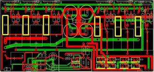
Ok guys, here it is. I spent many hours and tried to come up w/ a gainclone pcb w/ 6 lm3886 chips based on page 12 of the
bpa-200 pdf file, no dc servo's. Some of the components are meant to go underneith the pcb, since i wanted to keep traces short and size down. If anyone would like to critique the actual pcb, i can send them the expresspcb.com files
www.expresspcb.com is the place i got the software from, its a 2 layer board, and the ps includes 4 3900uF panasonic fc 35v caps... there is also space for bypass caps (of course those are optional). around the regulated section of the ps, there is space for 1kuF 25v fc caps and 100nF bypass caps.
I saw the thread down below about a bpa-200 kit. I think it'd be nice and easy to do a group buy on this, even if it was only 100 boards. I'd have to sorta reverse the board if people want to do a stereo board (ie, all the inputs and output are on the wrong side of the board for stereo, i'd need a mirror image, but something that wouldn't change the pinout. I spent about 20 hours on this...and this is my first attempt at a layout. If someone wants to critique it, and help me get this whole thing together, maybe in the future someone could arrange a group buy. Later!
-Matthew K. Olson
ps, email me through diyaudio, if i don't respond w/in 24 hours, i didn't get the email
Attachments
Peranders, i can send you the files for expresspcb, then you can see things a little better. Email me if you like and I'll send the files. I used pretty fat traces for the outputs. I need someone to really critique it and make sure my circuit looks good. Thanks!
-Matthew K. Olson
-Matthew K. Olson
Send me the files and I'll have a look...
It looks OK but we can make it better
switchmaster@hotmail.com
-Matt
It looks OK but we can make it better
switchmaster@hotmail.com
-Matt
One more thing, if you want it small why not use surface-mount? There are up to 3.5W SMT resistors out there, with 2W being cheap and easy to find. 1/2W is even smaller and easier to come by inexpensivly.
Caps and diodes can also be SMT, to make a tiny PCB and reduce noise to an absolute minimum.
-Matt
Caps and diodes can also be SMT, to make a tiny PCB and reduce noise to an absolute minimum.
-Matt
I don't want to use SMT because of easyness for beginners. Its a good point, but still. Also, some of the components are underneith, which hasn't been noted, but could be guessed. Especially under the space i have for the regulators heatsink. You're email is on its way. thanks
-Matthew K. Olson
thanks-Matthew K. Olson
1 Have you calculated any about traces and currents? They seem small to carry 30 A at least.
2 Output is very close to the input and 30 A currents?
3 Rectifier bridge, can it handle 30-50 A? Hardly. How about cooling? Now it can take 3-4 A only.
4 How have you done the grounding?
5 How much more performance do you get with 50% more parts than Thomas Madsen's "Das Modul"?
6 Where are the fuses?
I think you must pay attention to that this is a high current device and don't underestimate potential problems. Most of the group buy designers have been more or less professionals in pcb making and you are a student. With this I want to say that experience is important but in your case it's quite possible to achieve something good. But first you must build a prototype and have the whole amp concept ready, with transformers, switches, cooling arrangement etc. It's not enough to fix a pcb and then organize a group buy. This is an engineering task you have in front of you. It's not only to copy an application note.
Yes Peranders, I understand that this is the whole package. I've built many amplifiers now and I understand what is involved. Yes I realize my shortcomings, i'm a dental student, so duh, why do you think I posted it here rather than posting them on some website for sale????? Anyway, i'd like multiple people to look over it and see what they think. I like different opinions and things, so your suggestions will be taken into account. Maybe that bridge rectifier idea isn't so great on board etc. ...I'll look into it. If i'm really carrying 30A then I need an off board rectifier attached to a metal chassis (heatsinking). I don't mind spending the time it takes to get this right. So keep the suggestions coming. To all who posted interest...thanks! This might take a while to work on and get right.... but it can be done! Anyone else that wants the file to look over them just email me. Later!
-Matthew K. Olson
-Matthew K. Olson
peranders said:3 Rectifier bridge, can it handle 30-50 A? Hardly. How about cooling? Now it can take 3-4 A only.
Yep. There is no way to adequately sink the diodes.
I suggest once you get a good design proto via barebonespcb.com. Once you verify that it all works, no hum etc, then talk group buy. This is a pretty involved circuit to get right on the first try, even for experienced designers. Note that Brian has been working on LM4780 PCBs for some months and has still not qualified his design...and that is a simpler task than this.
You might also wish to breadboard the design if you haven't done so already...make sure it works like you expect without the servos.
There are pros and cons to the group buy format. One of the big cons compared to retail is that I think you owe it to your buyers to make a top quality product, because that is what people here expect. The market doesn't do any testing for you, people take it on faith that you have done this work yourself and arrived at a top-flight design. This is a lot of pressure for the organizer of the buy.i'm a dental student, so duh, why do you think I posted it here rather than posting them on some website for sale?????
I have a ptp amp just about up and running right now. I need or order a few other things before it all goes together, 6 chip monoblocks :-D They should be pretty sweet if they don't smoke on me. What got me to work on this pcb was the fact that doing everything ptp was cool and all, but a lot of work. And it seems like this hasn't been done in this format either.... so once again, it may be a while before the design if finalized, but i want to make sure its good. Thanks for the suggestions.
-Matthew K. Olson
-Matthew K. Olson
Yes! That is why I think PCBs are worthwhile for even simple designs, because sometimes you won't want to spend xxx hours hard wiring something that will ultimately go in a sub, etc.doing everything ptp was cool and all, but a lot of work
Good luck!
If you can't sell the pcb via a web site it isn't suitable for group buy either. As pointed out, top quality is required and 100% dedication is a must.Mattyo5 said:Yes I realize my shortcomings, i'm a dental student, so duh, why do you think I posted it here rather than posting them on some website for sale?????
Still, start first with building a prototype and see what you will have.
Bpa Pcb
I'm very interested in getting the PCB Express files. I have built Marchant dual 3886 board which is currently the hi High biamp driving Raven 3.1s.
If you have the schematic i would like that also.
The servos add complexity but seem to add stability and efficiencey to the design.
I'm interested in building a 200 watt per side 3886 amp and compare it to my my Mac Cormac dna 225.
http://www.imagematics.com/audio/Amp420.jpg
zagisrule! said:
Perhaps you should take a look at the heat sink suggested by National Semi for the BPA-200, then have another look at his design ... it will "kind-of" give you some of the dimensions, that is, you will need a significantly larger heat sink than that employed by the BPA-200.
The board will not come remotely close to supportting the current demands of a 300 watt amplifier -- figure this -- 30 amps is about the maximum that a #14 AWG wire can handle.
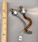
here are the type of rectifiers you'll be using:
Attachments
Ok, hang on. This amp doesn't necessarily need to do 300 watts. I'm going to be running 27v rails on my amp. I wanted higher current capability. Nothing has been finalized yet, which is exactly my point and exactly why I posted here on the board. I can certainly use external 35a bridge rectifiers... part #
gbpc3504di-nd from digikey.com
thats not a problem. Heatsinking is almost never a problem with me, thats why i'm not concerned about it right now. I'm into the bigger is better philosophy, so ...heatsinking needs can be figured in later. First i need to make sure the circuit works, THEN other things will fall into place. I know that I need to cater to peoples needs, such as a small heatsink perhaps ....which is fine, then either people can use a lower rail voltage or, only use 4 chips instead of 6. I hope i don't sound harsh, but it sounds like everyone is jumping into things, which i'm trying not to do, and which is why i need help Thanks for the suggestions. Keep em comin!
-Matthew K. Olson
gbpc3504di-nd from digikey.com
thats not a problem. Heatsinking is almost never a problem with me, thats why i'm not concerned about it right now. I'm into the bigger is better philosophy, so ...heatsinking needs can be figured in later. First i need to make sure the circuit works, THEN other things will fall into place. I know that I need to cater to peoples needs, such as a small heatsink perhaps ....which is fine, then either people can use a lower rail voltage or, only use 4 chips instead of 6. I hope i don't sound harsh, but it sounds like everyone is jumping into things, which i'm trying not to do, and which is why i need help
Thanks for the suggestions. Keep em comin!-Matthew K. Olson
Power issues
Maybe i am missing the point here but...
If you have + / - 50 volt rails (thats a 100v swing) at 300 watts you are only talkiing about 3 amps (?)
Where does the 30 Amp figure come from??
I agree you want fat traces on your PC board and I can tell you that the LM3886 will run hot when you drive them.
Bill
- Status
- This old topic is closed. If you want to reopen this topic, contact a moderator using the "Report Post" button.
- Home
- Amplifiers
- Chip Amps
- BPA-300 :-D Pcb designed!