Somebody tell me if there is anything wrong with this idea other than that it is dangerous because of the high voltage.
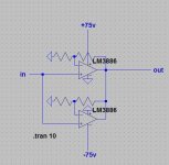
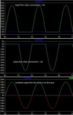
I have a +/- 75v ps from an amp, and I was thinking about using lm3886s with it. I would parallel 5 chips and set them up to run off the positive supply and gnd. The other 5 would run off the negative supply and gnd. The chips connected to the positive rail would only reproduce the positive half of the wave, while the chips connected to the negative rail would reproduce only the negative half. I know that I would have to set up virtual grounds at +/- 37.5v. I checked this setup in a simulator, and it should work.")
Can these chips handle voltage that high? In the datasheet it says that |v+| + |v-| has to be less than 84v, and in this case, it would be 75v.
I have a +/- 75v ps from an amp, and I was thinking about using lm3886s with it. I would parallel 5 chips and set them up to run off the positive supply and gnd. The other 5 would run off the negative supply and gnd. The chips connected to the positive rail would only reproduce the positive half of the wave, while the chips connected to the negative rail would reproduce only the negative half. I know that I would have to set up virtual grounds at +/- 37.5v. I checked this setup in a simulator, and it should work.
Can these chips handle voltage that high? In the datasheet it says that |v+| + |v-| has to be less than 84v, and in this case, it would be 75v.
Attachments
The circuit you have posted won´t work.
Using single supply you must set a voltage reference for each opamp at half the single supply in order to make it able to swing let´s say from 0-75V.
Have a look at the LM3886 datasheet how to connect for proper single supply operation.
If your transformer has got two primary windings (each 120V) I´d wire them in series so you effectively get half the secondary voltage.
IMO a better solution then the single supply approach.
Did you try the +-75V supply before or why "xplod" ?
regards
Jens
joensd said:Using single supply you must set a voltage reference for each opamp at half the single supply in order to make it able to swing let´s say from 0-75V.
That is correct if the chip is used by itself, so you get a push-pull amplifier. I only need each set of chips to do one thing--one set will push (+v), while the other set will pull (-v).
Did you try the +-75V supply before or why "xplod" ?
No, I did not try this before. And the xplod is from sony xplod subs that i used to have.
If you want something that will work, just build a bridge amp.
The transformer can be re-wired as a full-wave center tap with two diodes to give 75V, the bridging allows for a 150V P-P into the speaker.
If you're bored, build the bridge with the patented 'X' feedback scheme as suggested by Nelson Pass.
I could show you how to make your scheme actually work, but it will exceed the Vceo of the output devices in the chips.
joensd said:The circuit you have posted won´t work.
You took the words out of my mouth...
How can a circuit that doesn't work be simulated?
carlosfm said:
You took the words out of my mouth...
How can a circuit that doesn't work be simulated?
The simulator doesn't know that it has to blow up the chips when it goes over the max voltage..
The map is not the world!
Jan Didden
"LM3886" and "super amplifier" are terms I'm not sure go together too well. However, if you want to get some use out of your 75-0-75Vdc PS (which I presume means about a 52-0-52 Vac trransformer) here's an option that is not "super" could be pretty damn impressive:
Connect the two secondaries in parralel to get a 26-26 transformer. There will be no centertap so you need to look as Rod Elliot's project #43, fugure 2. Build a PS like this wit suitable mods for the voltage and current involved suvh as providing +&- power to the opamps by using a couple of zenners. The higher rails have no impact here because the opamps are just dealing with the DC offset. This gets you about a 35-0-35 PS (with just about the most perfect 0V dc offset you'll ever see.
Now, on the same website check out projects #9 or #81 and also read the artical on biamping. Choose one of the projects and buy the PCBs (Rod deserves the trade!)
Depending on the current available from you reconfigured transformer and PS, you should be able to drive 4 or 6 LM3886's very well. Configure these as either a bi- or tri-amp. You should be able to get everthing into one fair sized box.
Now you just need to mod your existing speakers if they don't already have bi/tri amping provisions. This may not ne a super amp with regard to power level, but if you select the XO points right and work carefully you stand a fair chance of getting a "super audio system" emphasis on system.
This is just a suggestion, of course. It's the best way I can think at the moment to get something really remarkable from the combination of LM3886's and the trandformer you describe.
"Connect the two secondaries in parralel to get a 26-26 transformer"
Gee, I think someone already said that. If its salvage from a commercial amp it likely won't have 52-0, 52-0 secondaries. Most likely it will have 52-0-52
"The transformer can be re-wired as a full-wave center tap with two diodes to give 75V, the bridging allows for a 150V P-P into the speaker."
"Depending on the current available from you reconfigured transformer and PS, you should be able to drive 4 or 6 LM3886's very well. Configure these as either a bi- or tri-amp. You should be able to get everthing into one fair sized box."
Unless you bridge, you will need to use an output coupling cap for each LM3886 since you only have a single-ended supply. You need to re-read the ESP article.
carlosfm said:
You took the words out of my mouth...
How can a circuit that doesn't work be simulated?
Can you tell me why this circuit doen't work?
janneman said:
The simulator doesn't know that it has to blow up the chips when it goes over the max voltage..
Jan Didden
How will that be going over the max voltage? Each chip would only see 75v, and the max is 84v.
sam9 said:
Now you just need to mod your existing speakers if they don't already have bi/tri amping provisions. This may not ne a super amp with regard to power level, but if you select the XO points right and work carefully you stand a fair chance of getting a "super audio system" emphasis on system.
I wanna make this amp to drive some subs, not full range speakers. I want one high-power channel rather than multiple lower-power channels.
I suppose you can't settle for that this is not a good idea. One thing you have really forgotten, the parameter "input common mode voltage". What happens when the inputs are very near GND for the upp LM3886 and near GND for the lower LM3886? What happens to the upper LM3886 when you apply negative voltage and vice versa for the lower one? Can the outputs go to exactly 0 Volts? => Huge crossover distortionxplod1236 said:Can you tell me why this circuit doen't work?
Can you apply -75 volts at the upper LM3886? Lot's of questions. Try to answer those first.
Yes, the supply pin of each chip see 75V. But the output pin of each chip will see the full voltage swing of +75-(-75)=150VEach chip would only see 75v, and the max is 84v
Even if you run them with +/-35V supply, I still won't recommend this push-pull arrangement. Cos LM3886 is not rail to rail, and its clipping is not symmetric. I guess there will be lots of even harmonics if you do so.
banana said:
Yes, the supply pin of each chip see 75V. But the output pin of each chip will see the full voltage swing of +75-(-75)=150V
Would adding output transistors keep the chip output from seeing 150v?
xplod1236 said:
Would adding output transistors keep the chip output from seeing 150v?
There are already output transistors in the chips.
Wouldn't modifying the transformer to make the secondaries in //, or, for that matterr, another transformer, be not infinitely simpler than what you are trying to do? Especially since you can do the other transformer yourself. The other thing like adding transistors, you cannot do without help from the forum. Because of the wide range of expertise and opinions, which will be a hell of a job to sort out as to what is sensible, what is non-sense, that's doomed to failure. Not speaking about the fact that the current circuit doesn't work as drawn anyway. At any voltage than exactly 0 volts (and that's not really very usefull to drive a speaker
) the two amps are just fighting to absorb each others output voltage, one is trying to drive the other as a load. The top amp cannot give neg output voltage, and the bottom one cannot give pos output voltage, yet the outputs are connected.Jan Didden
djk said:"Would adding output transistors keep the chip output from seeing 150v?"
No, build a bridge amp.
2 LM3886 =100W/16R
4 LM3886 = 200W/8R
8 LM3886= 400W/4R
10 LM3886 would give you a little headroom for a 4R amplifier.
What's the max voltage swing I would obtain from the bridge amp? The rails are +/-72.5v.
How big would the output caps have to be? Would I need a cap for each chip or just one for the combined output?
joensd said:Xplod, does your transformer have two primary windings?
That´d really be the simplest solution.
There is one primary winding, and one center tapped secondary. The secondary is 52-0-52.
"What's the max voltage swing I would obtain from the bridge amp? The rails are +/-72.5v."
A bridge amp would swing the full, available voltage
"How big would the output caps have to be? Would I need a cap for each chip or just one for the combined output?"
No output cap needed on the bridge amp, the output cap was only needed if many smaller amps for bi-amping were to be used.
"There is one primary winding, and one center tapped secondary. The secondary is 52-0-52."
That is what I thought. Two diodes and a single 10,000µF 80V cap are all you need to build a supply for a 400W/4R amplifier.
apexjr has 10,000µF 80V caps for $3.95 each, or some nice computer grade that would make 34,000µF at 100V for $11.90
http://www.apexjr.com/capacitorsR.html
- Status
- This old topic is closed. If you want to reopen this topic, contact a moderator using the "Report Post" button.
- Home
- Amplifiers
- Chip Amps
- lm3886 super amp