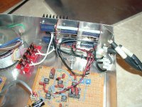
I have recently completed the attached prototype of what I guess can be called a 3way monoblock Gainclone. It is a chassis that has a 3way active crossover with 3 of Brian's Gainclone boards.
The attached picture is before I completed the final grounding scheme. I am using this prototype with a open baffle speaker design I have been working on for some time. This design has a load impedence of less than 4 ohms in both the woofer and midrange passband. I find that the GC's run out of power on demanding rock concert DVD's but otherwise sound fantastic. I know that the GC is not the best choice on driving loads below 4 ohms but the sound of this configuration is so encouraging I would like to explore all posibilities.
I am in the process of installing a higher power Torroid but am curious if anyone has had any experience with using larger capacitors between the rectifier board assembly and Brian's gainclone boards?
I'm aware of the minimal design approach of the gainclone but am also aware of the fact that under dynamic demands the 1 to 1.5Kuf capacitors on these boards will definitely not be able to deliver the instantaneous requirements of some program material/speaker efficiency demands.
Are these requirements best met by the rectifier board assembely and its associated interconnect wiring and all of it's reactive impedence considerations, or could this dynamic requirement be met better by a capacitor bank between the rectifier assembly and the GC board?
BobK
Attachments
BobK said:
I'm aware of the minimal design approach of the gainclone but am also aware of the fact that under dynamic demands the 1 to 1.5Kuf capacitors on these boards will definitely not be able to deliver the instantaneous requirements of some program material/speaker efficiency demands.
That should be easily solved if you using a three-way active approach. Simply add more external capacitance on the module going to the bass unit. Up to 10000uF should be finely handled by the diodes and would provide a good punch control.
A 200 to 300VA toroid should be enough for dynamics and should not let the units run out of power.
Carlos
I understand that the 'best' way to add capacitance for a GC is to use a regulated supply. I am currently building one with 10,000 uF caps and LM338 regulators.
You can get more information on Pedja's web site .")
You can get more information on Pedja's web site .
I have 250VA transformers on order and was also considering 10kuf's on the bass amplifier. This would allow the reserve energy for the low end demands but keep the mid and highend performance everyone likes about the GC.
Pedja's postings about regulated supplies are interesting, I might give one a try. In the past I have not been impressed with the sound of amplifiers with regulated supplies but they have been evaluated running full range.
Pedja's postings about regulated supplies are interesting, I might give one a try. In the past I have not been impressed with the sound of amplifiers with regulated supplies but they have been evaluated running full range.
In the past I have not been impressed with the sound of amplifiers with regulated supplies
may i ask - what amps did you listen to....?
It's been a number of years ago that I listened to a regulated supply amp, and am embarrased to say I don't recall the commercial amplifier we auditioned. One unit was a heavily modified Dynaco 400 than one of my friends built. The unit tested very well but sonicly was somewhat disappointing.
Nuuk said:I understand that the 'best' way to add capacitance for a GC is to use a regulated supply. I am currently building one with 10,000 uF caps and LM338 regulators.
I made a regulated PSU for my sub (two paralleled OPA549s) with LM338 and the result is fantastic.
Yes, with 10,000uf before the regulators.
A few days ago I was given a nice box.
I'm also scavenging an old amp, that has a (apparently) good trafo, but voltage is +/- 31v.
So, by coincidence, I'm just starting a regulated PSU with LM338 for another GC... NOW!
Carlos, good to hear you've had good success with your regulated supplies. Again, the experience I've had is dated, and was always evaluated full range. I could see advantages in a sub-amp application. In my design the three way unit I posted will be used with a sub, so the woofer amplifier will be used from 80 to 300Hz.
Nuuk said:I understand that the 'best' way to add capacitance for a GC is to use a regulated supply. I am currently building one with 10,000 uF caps and LM338 regulators.
That's not necessarily the best way, and I would probably not think of a regulator as a way to add capacitance. Perhaps a capacitance multiplier might be that.
The only thing in common between capacitors and regulators is that both lower the impedance, but the former does so in just one area.
A regulator should have other more important chores, like keeping a constant voltage no matter the voltage/current demands, lower and flatten the output impedance of the supply, lowering noise, etc.
The problem is that to do that they imprint their mark on the sound, because most use feedback to do so. It maybe a matter of taste also, so it's a debatable question whether a regulated amp sounds best than a properly designed one.
By properly designed I mean the transformer should be large enough and the capacitance attend the demands of the sound. On the tests I have done it became a taste option, if you liked good and controlled bass, whether to use up to 1500uF caps for better mid and highs, or more than that for better lower frequencies. In my opinion you should power the speakers separately.
There's an important tip though: a regulator should have better specs than the amp it's powering. Like higher bandwidth. In fact a regulator IS an amplifier.
Pedja's regulator, using an LM338, should be a very good place to start from.
Carlos
carlosfm said:
I'm just starting a regulated PSU with LM338 for another GC... NOW!
This afternoon I
 and it's done.
 It took a little longer, I had to open the trafo, it was a CT.

Regs with trimmer pots, adjusted for EXACTLY +/- 31.0 volts.
PSU is done, my modules with LM3886 are done for months, now to finish the box, some days.
Let's see if this thing is even better than my GC power amp, on my main system.
Later I'll report if it's
 or
or  .
.carlmart said:............
There's an important tip though: a regulator should have better specs than the amp it's powering. Like higher bandwidth. In fact a regulator IS an amplifier.
Hi,
Indeed a regulator IS an amp. But there are some major differences over an audio amp. A regulator is usually loaded with a big capacitor. This will give it low impedance at higher frequencies relaxing bandwidth requirements, but anyway GBP can be made easily 100MHz (without the loading cap) when build with discrete transistors. Second, a linear regulator is always running in class-A.
What is also important is its transient behaviour. A regulator feeding an audio amp should have no overshoot and ringing artefacts. Most IC regulators do have that however.
IMHO such a regulator should have constant output impedance from DC to the end of the band the connected amplifier is used, to be “invisible”. At low frequencies the regulation action of the regulator takes care of that and at higher frequencies the loading capacitor will do. Building a good regulator that have no imprint on the audio is not an easy task.
On the other hand the small smoothing cap in the original Gaincard PSU is part of its flavour
Cheers
considering 10kuf's on the bass amplifier
Are you using different diode bridges for the sub amp with the same tx? Using only 1 tx a second bridge must be used to have not 10000u in the GCs.
Miguel
Well...
Summarizing, the only difference from this GC (let's call it RGC - regulated, with LM338s) and my power-amp on my main system (let's call it URGC) is really the PSU.
Both are BIGCs, on my PCBs, with OPA627 as buffer.
The amp modules are exactly the same: same caps, same regs for the 627s, same everything.
Both use MUR860 as rectifiers, on my small PCBs.
My RGC has 4,700uf caps on the rectifier board, and another 2,200 uf on the regulator board.
The URGC just has 1,000uf.
Results?
The RGC has very goof bass, as I expected from the results i've got on my sub.
The rest... crap!
That midband magic disappeared, that treble got muted, that impressive transient speed of my URGC is gone, detail is gone, harmonics disappeared. 
This seams like a normal amp. 
Hi-Fi, not high-end.
I don't believe it's the crap test wires and connectors, because they are the same in every amp I make.
I'm gonna keep this thing -in some days on my bench, and then test again.
I'd like to hear other people's oppinions.
Nuuk, have you made the PSU?
Summarizing, the only difference from this GC (let's call it RGC - regulated, with LM338s) and my power-amp on my main system (let's call it URGC) is really the PSU.
Both are BIGCs, on my PCBs, with OPA627 as buffer.
The amp modules are exactly the same: same caps, same regs for the 627s, same everything.
Both use MUR860 as rectifiers, on my small PCBs.
My RGC has 4,700uf caps on the rectifier board, and another 2,200 uf on the regulator board.
The URGC just has 1,000uf.
Results?
The RGC has very goof bass, as I expected from the results i've got on my sub.
The rest... crap!
That midband magic disappeared, that treble got muted, that impressive transient speed of my URGC is gone, detail is gone, harmonics disappeared.
This seams like a normal amp.
Hi-Fi, not high-end.
I don't believe it's the crap test wires and connectors, because they are the same in every amp I make.
I'm gonna keep this thing
-in some days on my bench, and then test again.I'd like to hear other people's oppinions.
Nuuk, have you made the PSU?
Carlos, I was advised to remove the 100 uF's from the chip pins and use 100 uF instead.
Also you need to have the regs as close as possible to the chips and those 100 uFs act as the output caps for the LM338's.
All details from the totally brilliant and hard-working Pedja who also finds time to study philosophy as well! How does he do it?
Also you need to have the regs as close as possible to the chips and those 100 uFs act as the output caps for the LM338's.
All details from the totally brilliant and hard-working Pedja who also finds time to study philosophy as well!
How does he do it? Nuuk said:Carlos, I was advised to remove the 100 uF's from the chip pins and use 100 uF instead.
You mean replace the 1000uf for 100uf?
That makes sense to me.
I'll try that, I have this as a bunch of wires, no problem.
Maby I'll remove the 100uf I have on the output of the LM338s
and (I'm reluctant to leave them with nothing ) put 0.1uf caps.Yes, maby an RGC needs to be quite different.
If you remove the 100's from the output of the regulator circuit but have the regs as close as possible to the chip pins, then they are still effectively on the the ouput of the regulators!
Exactly Carlos - your English continues to improve wonderfully!
You mean replace the 1000uf for 100uf?
Exactly Carlos - your English continues to improve wonderfully!
- Status
- This old topic is closed. If you want to reopen this topic, contact a moderator using the "Report Post" button.
- Home
- Amplifiers
- Chip Amps
- Gainclone Power Supply Design