Has anyone ever implemented a circuit to turn on an Amp when you get a 12 volt signal from a reciever/processor?
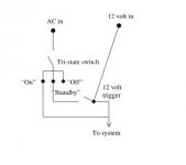
I'm thinking of having a tri-state switch that has an "On" state which ignores the 12 volt signal, an "Off" state to turn off power completely and a "Standby" state that would switch the amp on when the 12 volt signal is detected.
Here's a conceptual drawing to help explain. I don't know how to draw a proper circuit diagram, this is just a high level idea....
Attachments
I've built a very simple circuit that has worked without a problem for 8 months now. I got a 12V DC 1 amp wall wart and plugged it into the switched AC outlet of my receiver. I used this 12V output to control a 12 V relay with a 30A (@>120 AC Volts) contacts. I use the relay contacts to switch the AC to several components, among them a 1200 Watt Crown Pro Amp. I bought the wall wart and relay from All Electronics for less than $10.
This is how I plan to do it: in every amp/active crossover/whatever I create, I will put this circuit:
If the amp/... has a power button, it will be connected to one of the enable inputs. On the back I'll have 2 trigger connectors (probably a serial connector), one input and one output. The output pins are directly connected to the pins on the input connector.
The triggers (8 of them, 1 ground => serial connector) will be controlled by a relay driver in my preamp. The driver is capable of sourcing 200mA per trigger line.
In the amp/... one of the input pins is connected to one of the enable pins of the above circuit. If you have more than 8 things you want to remotely control, you can always use logic gates etc. to have more possible "control codes".
The only drawback I see to this is that you need an appropriate voltage in the amp/.... If you don't want to use the device's power supply for this, you'll have to add a small separate supply. A 78xx & a small transformer is pretty small, so that shouldn't be too much of a problem.
*Oh btw, if you want tri state with this circuit simple put a 240V switch in series with the AC input. You can then mount it on the back next to the AC connector. Then you'll have your: always off, always on (with another, simple switch on the front) & on on trigger signal.
An externally hosted image should be here but it was not working when we last tested it.
If the amp/... has a power button, it will be connected to one of the enable inputs. On the back I'll have 2 trigger connectors (probably a serial connector), one input and one output. The output pins are directly connected to the pins on the input connector.
The triggers (8 of them, 1 ground => serial connector) will be controlled by a relay driver in my preamp. The driver is capable of sourcing 200mA per trigger line.
In the amp/... one of the input pins is connected to one of the enable pins of the above circuit. If you have more than 8 things you want to remotely control, you can always use logic gates etc. to have more possible "control codes".
The only drawback I see to this is that you need an appropriate voltage in the amp/.... If you don't want to use the device's power supply for this, you'll have to add a small separate supply. A 78xx & a small transformer is pretty small, so that shouldn't be too much of a problem.
*Oh btw, if you want tri state with this circuit simple put a 240V switch in series with the AC input. You can then mount it on the back next to the AC connector. Then you'll have your: always off, always on (with another, simple switch on the front) & on on trigger signal.
Re: need explanation
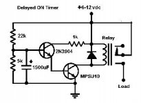
The 1N4148, 1N4004 & BC547 are about the most general available diodes & NPN transistor you can find, in Europe that is. If you can't find them replace as follows:
1N4148: general low current diode (can easily fit in 5mm footprint)
1N4004: general diode (1A 100V) (fits just into a 7.5mm spaced footprint)
BC547: general NPN transistor
If you're not sure with what to replace, here are the datasheet to give you a general idea. They are from OnSemi (Motorola). As these are general parts, the characteristics should be the same no matter what brand you have.
BC547: datasheet
1N4148: datasheet
1N4004: datasheet
Know that I haven't tested this circuit yet! I'll probably will do so today. Note that the BC547 can only source 100mA continuously. If you're going to use a low voltage relay (eg. 6V) you might need to use another transistor, one that can source more current.
The "En Signals" are indeed the trigger signals.hams said:Can some explain what the following parts from the suggested schematic:
1N4148
1N4004
BC547
Are the "En Signals" the trigger signals?
thanks.
The 1N4148, 1N4004 & BC547 are about the most general available diodes & NPN transistor you can find, in Europe that is. If you can't find them replace as follows:
1N4148: general low current diode (can easily fit in 5mm footprint)
1N4004: general diode (1A 100V) (fits just into a 7.5mm spaced footprint)
BC547: general NPN transistor
If you're not sure with what to replace, here are the datasheet to give you a general idea. They are from OnSemi (Motorola). As these are general parts, the characteristics should be the same no matter what brand you have.
BC547: datasheet
1N4148: datasheet
1N4004: datasheet
Know that I haven't tested this circuit yet! I'll probably will do so today. Note that the BC547 can only source 100mA continuously. If you're going to use a low voltage relay (eg. 6V) you might need to use another transistor, one that can source more current.
hams said:Has anyone ever implemented a circuit to turn on an Amp when you get a 12 volt signal from a reciever/processor?
I'm thinking of having a tri-state switch that has an "On" state which ignores the 12 volt signal, an "Off" state to turn off power completely and a "Standby" state that would switch the amp on when the 12 volt signal is detected.
Here's a conceptual drawing to help explain. I don't know how to draw a proper circuit diagram, this is just a high level idea....
I had a friend making such a circuit on a nice PCB for my ICG power amp. See:
http://2bak.homepage.dk/gainclone.htm
However this circuit is made so that the turn-on circuit itself is always on (LED on front is then red), and cannot be turned off except by plugging out the AC power mains cable.
However a special power switch connected to this circuit makes it possible to turn on the Gainclones pwr-supply without a 12v trigger from the source (pre-amp) and LED goes to green (the two-color LED is part of the circuit, not part of GC's pwr-supply).
Thus with this switch I can turn-on my GC if I do not have my (Thule Audio) pre-amp with me and it's I/O data output, e.g. if I wanted to use my GC with a pre-amp without such a I/O data 12v output.
I can mail you circuit if you want me too, however don't ask me about details on it, 'cause I didn't make it. Perhaps I can also mail you the pcb-layout files and the partlist, if I ask my friend to send them to me.
See also pics here:
http://2bak.homepage.dk/12_volt_trigger_turn.htm
/Jan
I was wondering exactly how to make a power on switch using a momentary switch.
The idea being that if the mains went off while my system was unattended, the preamp/buffer circuit would come back on when mains power was restored, but the power amp would not until the momentary button was activated.
Presumably this would be done using a relay with the momentary switch.
The idea being that if the mains went off while my system was unattended, the preamp/buffer circuit would come back on when mains power was restored, but the power amp would not until the momentary button was activated.
Presumably this would be done using a relay with the momentary switch.
Nuuk said:I was wondering exactly how to make a power on switch using a momentary switch.
The idea being that if the mains went off while my system was unattended, the preamp/buffer circuit would come back on when mains power was restored, but the power amp would not until the momentary button was activated.
Presumably this would be done using a relay with the momentary switch.
In fact I cannot turn OFF the relay/power-on-circuit, in fact it is ON 24-7 (it's small trannie doesn't doesn't cost much to have on all the time).
The reason why I wanted this switch (placed on the back, 'cause rarely used ) was to have the option to turn on my Gainclone pwr-supply (via the relay) if I didn't have the 12 v i/o data cable connected.
Thus if the mains suddenly went off, and it came back on again, the standby circuit would be ON (red) at once !
Of course if I went on holiday or something I would turn of the Gainclone entirely, including the power-on circuit by removing the mains cable from it's behind ;-)
/Jan
Nuuk
The timer board I am sending will do this for you -) I will include 10A suitable relay,loss of supply will cause the board to re-time (adjustable from 1sec to 3minutes
Peter, you are an
 (even if your SOH thinks you are sometimes a
  ).
). ")
A turn on switch with the use of a push button ehNuuk said:I was wondering exactly how to make a power on switch using a momentary switch.
The idea being that if the mains went off while my system was unattended, the preamp/buffer circuit would come back on when mains power was restored, but the power amp would not until the momentary button was activated.
Presumably this would be done using a relay with the momentary switch.
?Take a look at my website:
1) Push Button -> Switch function: http://members.lycos.nl/anthonyvh/index.php?page=push
2) Relay Switch: http://members.lycos.nl/anthonyvh/index.php?page=power
Combine that with a power supply (I think the max. voltage would be 12, I don't think the inverter chip can handle much more) and you have what you want. I'm going to use it in my JLH. I'll probably add a PCB for a simple power supply to my site tomorrow. Nothing special, just a 78xx IC with a small heatsink & a total of +- 1500µF buffer caps.
Take a look at my website:
Yes, that looks like what I was talking about.
Just to make sure, if the mains supply fails, the amp will not be powered up when it is restored until the push button is pressed again. Is that correct?
If so then I won't waste hours 're-inventing the wheel' on DD. I'll just include a link to your very informative pages.
I mains fails, and powers up again the situation is like this on mine:
The standby circuit will be turned on, the Gainclone PWR-supply not.
To power-on the GC pwr-supply I must turn on my Thule preamp again, 'cause this one turns off by automatic, if mains fails.
But perhaps I misunderstand what your point is.. ;-)
/Jan
The standby circuit will be turned on, the Gainclone PWR-supply not.
To power-on the GC pwr-supply I must turn on my Thule preamp again, 'cause this one turns off by automatic, if mains fails.
But perhaps I misunderstand what your point is.. ;-)
/Jan
But perhaps I misunderstand what your point is.. ;-)
When I have used a buffer circuit with my GC's, I notice that there is a momentary high DC offset on the output of the buffer circuit when they are powered up.
This could cause a problem if that DC offset is then amplified by the GC circuit so it is better to wait for a short time (this time varies according to the buffer circuit that is used and it's PSU design), before powering up the GC circuits.
If the mains power is broken due to a power cut, and then comes back on again, the GC circuit will be powered up at the same time as the buffer.
This has happened to me once recently. Fortunately, apart from a nasty pop on the speakers, it didn't do any damage but it is a situation that I would rather avoid (especially with my delicate and difficult to replace Godmans 201 drivers).
So, ideally it is best to have a system where if the mains is cut, power will not be restored to the power amps, either without a delay caused by a suitable circuit, or without the user manually switching the power back on.
Of course, this situation can also be solved by using a Velleman speaker delay unit (model 4700) which incorporates a switch on delay but some people do not like to pass the signal through the relays of the protection module, and for those people, the alternative is the one that I have mentioned above.
Well, as far as I can tell, it won't turn on. The inverter chip sees a logical 0 at the gate with the switch connected to, so it's output is 1, this goes to the 2nd inverting gate which then results to a 0 at the output. So you have to push the button to turn the amp back on.Nuuk said:
Yes, that looks like what I was talking about.
Just to make sure, if the mains supply fails, the amp will not be powered up when it is restored until the push button is pressed again. Is that correct?
If so then I won't waste hours 're-inventing the wheel' on DD. I'll just include a link to your very informative pages.
Off course, if you have your preamp turn on the gainclone trough a trigger line, it will power up as soon as the mains is back on, but that's quite logical.
I would be honoured to have my site linked on DD
. Thanks!- Status
- This old topic is closed. If you want to reopen this topic, contact a moderator using the "Report Post" button.
- Home
- Amplifiers
- Chip Amps
- 12 volt trigger