I have some doubts in my mind about the input impedance of a common non-inverting op amp circuit which appears in the data sheet for the LM4780 chip amp, and my research has not revealed a definitive answer.
Here's a couple of simple questions for which I am seeking the correct answer, and why:
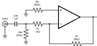
1. What is the AC input impedance of the circuit below, for frequencies above the f3 point determined in part by Cin ?
2. What value should RB actually be to balance the DC input offset currents, so that the output DC offset is minimised?
Please reply if you know the correct answer. I would prefer not to waste bandwidth with any off-the-top-of-my-head guesses.
Here's a couple of simple questions for which I am seeking the correct answer, and why:
1. What is the AC input impedance of the circuit below, for frequencies above the f3 point determined in part by Cin ?
2. What value should RB actually be to balance the DC input offset currents, so that the output DC offset is minimised?
Please reply if you know the correct answer. I would prefer not to waste bandwidth with any off-the-top-of-my-head guesses.
Attachments
Hi,
your question is about non-inv. opamp but your picture shows inv.amp.........wasting bandwidth?
Answers are here http://en.wikipedia.org/wiki/Operational_amplifier
Regards
your question is about non-inv. opamp but your picture shows inv.amp.........wasting bandwidth?
Answers are here http://en.wikipedia.org/wiki/Operational_amplifier
Regards
DC offset is caused by other things as well as by the PD due to input currents!
But to answer your question, 14K for Rb is about right (20k in parallel with 48k). But frankly, unless your input bias currents are high, I wouldn't have though it will make much difference.
But why is this an inverting amp when you call it non-inverting?
But to answer your question, 14K for Rb is about right (20k in parallel with 48k). But frankly, unless your input bias currents are high, I wouldn't have though it will make much difference.
But why is this an inverting amp when you call it non-inverting?
Glenn, first I think you should take a close look at the datasheet of LM4780 and also AN-1192 and also application notes for the LM4780.
The 47 k is totally unnecessary. If you want to do it really right the 953 ohms resistors should be 20 kohms if you want to minimize the offset voltage. This resistor had also a purpose of protection during power down and the recommend value was 1 kohms.
The input impedance = Rin => 1 kohms in your case => the input cap is way too small. 10 uF at least should it be. f = 1 /(2*pi*R*C)
EDIT: I have checked the datasheet and I see that you have taken the exact circuit as suggested but something is wrong, according to me. Am I wrong?
Whoops, I actually meant an inverting amp circuit. My apologies.
The wikipedia says Zin = Rin for the inverting amp, as does every other reference I could find. In which case, Cin = 1 uF is indeed way too small for this circuit as audio amplifier:
f3 = 1 / ( 2 . pi . C . Rin || Ri ) = 163 Hz (no bass!)
(where Rin || Ri = 979 ohms)
Also, RB should really be Rf || ( Ri + Rin) = 14118 ohms, rather than the Rf || Ri = 953 ohms given in the circuit.
Does anyone think that NS stuffed up these two aspects of this particular app circuit for the LM4780?
I think NS has done a little too much copy and pasting I'm afraid.glennb said:Does anyone think that NS stuffed up these two aspects of this particular app circuit for the LM4780?
Ouroboros said:953 Ohms would be correct if you didn't have the input capacitor or course.
Yes, because then Ri would be DC coupled to a low source resistance to ground, which is the general assumption made for calcuating RB = Ri || Rf in a classic inverting opamp circuit. I think NS failed to realise that adding Cin actually changes the DC considerations around the opamp inverting input.
peranders said:...The 47 k is totally unnecessary....
Yes, without the 47K there is still a DC charge path for Cin, which is through Ri and Rf.
The resistive load on the input which determines the f3 then becomes Ri alone, ie.
f3 = 1 / ( 2 . pi . Ri . C )
It then follows that RB = Rf, as there is now no DC path through Ri.
My beef with the inverting circuit is that to have a reasonable input impedance (say >20K) and a resonable gain (say 20) requires Ri = 20K and Rf = 400K. In my mind, 400K is too large for a feedback resistor. The overall noise would be higher and the DC offset input currents would make the DC output offset voltage much higher.
peranders said:..I have checked the datasheet and I see that you have taken the exact circuit as suggested but something is wrong, according to me. Am I wrong?
I cut/paste the application circuit from the LM4780 PDF, wiped out the power supply connections, and moved the Rf label from below the resistor to above.
Has anyone measured the distortion of a 3875 (or similar) in inverting and non-inverting modes. Or can tell if they sound any different?
Many ordinary op-amps measure better in an inverting mode as the elimination of the common-mode signal keeps the input stage operating in a more linear region. I guess the same is likely to be true for power op-amps, although an inverting mode will need an input buffer stage to drive the relatively low-Z input of the inverting power stage.
Many ordinary op-amps measure better in an inverting mode as the elimination of the common-mode signal keeps the input stage operating in a more linear region. I guess the same is likely to be true for power op-amps, although an inverting mode will need an input buffer stage to drive the relatively low-Z input of the inverting power stage.
Hi,peranders said:The 47 k is totally unnecessary.
placing resistor in input of inv. opamp is good for stability. If input isn't pulled to ground (thru source impedance) for any reason (bad input switch, pot or in experimental phase), inv. opamp will oscilate. My simple idea is placing same value like RF (20 or 22k here).
Regards
Hi,
From my experience, LM xxxx amps will start to oscillate if gain is below 1 what is also depending of PCB or P2P design. If gain is below 10 or so, opamp will be temporary unstable (in one part of output signal-waveform ) but not all the time.
NS datasheet isn't correct, IMHO. (obviously copy/paste errors)
Regards
peranders said:If you want to do it really right the 953 ohms resistors should be 20 kohms if you want to minimize the offset voltage.

Rb is fine.
It should be Ri//Rf.
If you want to minimize DC.
peranders said:The 47 k is totally unnecessary.
moamps said:Hi, placing resistor in input of inv. opamp is good for stability. If input isn't pulled to ground (thru source impedance) for any reason (bad input switch, pot or in experimental phase), inv. opamp will oscilate. My simple idea is placing same value like RF (20 or 22k here).
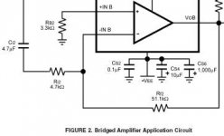
The LM4780 data sheet also contains the following circuit snippet, indicating that a resistor to ground (from the Ci2 Ri2 junction) is not really necessary.
They way I see it, the - input is pulled to ground (ie. a DC path to ground) by Rf. The + input is pulled to ground by RB, and by definition the + and - inputs are at the same potential, so the - input will therefore be at ground. Any comments?
Attachments
peranders said:Ok, totally right if you have the amp has the input unconnected but the gain will be much less than 10, in fact 0.5 only. Isn't this reasons for instablility? I haven't tested this.
There will be no "gain" delivered through the effective 47K + 1K input resistance (to give your overall 0.5 gain = 20K / (47K+1K) )because the input end of the 47K is grounded !!!!
I don't think the stability is affected between having the 47K there and simply removing it.
glennb said:They way I see it, the - input is pulled to ground (ie. a DC path to ground) by Rf. The + input is pulled to ground by RB, and by definition the + and - inputs are at the same potential, so the - input will therefore be at ground. Any comments?
That's correct. And to complete the picture, consider that, if you like, the op-amp output will "move" to ensure that there is always 0V at the inverting input. An input signal will attempt to pull the - input one way, and the output swings the other way to pull the input back to zero.
When analysing this configuration, it helps to consider the currents in the two resistors
Cheers,
Mark
Hi,glennb said:The LM4780 data sheet also contains the following circuit snippet, indicating that a resistor to ground (from the Ci2 Ri2 junction) is not really necessary.
look at picture below, you will find RIN1 act like this resistor.
We talk here about AC gain, not DC.
Regards
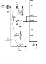
Attachments
Should be: Input impedance of an inverting op amp
Cin1 & Rin1 are isolated from interacting with Cin2 & Rin2 because the Audio Input A is driven by an AC low impedance source, and DC can't flow around them because there are two caps in the way.
Therefore the 47K at Rin1 does not influence the AC gain, DC operation point or stabilisation of op amp B and its associated components Ci2, Ri2, RB2, Rf2.
moamps said:Hi, look at picture below, you will find RIN1 act like this resistor.
We talk here about AC gain, not DC.
Cin1 & Rin1 are isolated from interacting with Cin2 & Rin2 because the Audio Input A is driven by an AC low impedance source, and DC can't flow around them because there are two caps in the way.
Therefore the 47K at Rin1 does not influence the AC gain, DC operation point or stabilisation of op amp B and its associated components Ci2, Ri2, RB2, Rf2.
- Status
- This old topic is closed. If you want to reopen this topic, contact a moderator using the "Report Post" button.
- Home
- Amplifiers
- Chip Amps
- Input impedance of a non-inverting op amp?