I'm a newbie to DIY GC building, and do need some advise regarding grounding of my GC-amp project.
I'm building a 3886TF chip P2P amplifier with 2 rectifier boards, each consisting of 4 MUR 860 diodes. PS caps 2 X 2200 uf Elna 63 V pr. rail., 1 toroid transformer with 2 secondaries, each gives 21 V before the bridge. Two secondary leads to each bridge. The grounding layout is separate grounding of the Caps from each chip, then to the mains grounding star. Groundings from the chip are led to a common grounding point, therafter to the mains g-star.
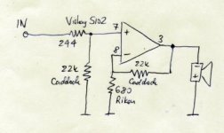
Other component values: 22k rf, 220 ri & 22k r and 22 k rm. 680 r from earth to v-.
I'm using a wooden cabinet of norwegian pinewood, then using 4 mm "suger bits" connectors as the grounding stars.
I have measured the rails to 27.4 v over the caps, and the idling DC to 5.5 mv and 6.0 mv respectively across the speaker terminals using a 10 ohm resistor (following advice from NUUK's website).
Then, when I'm connecting source (pre-amp) throught the phono-in plugs, I can hear a loud brum from the speakers. I assume there is a ground loop in my system, can anybody advice me what I have done wrong?
FMB
I'm building a 3886TF chip P2P amplifier with 2 rectifier boards, each consisting of 4 MUR 860 diodes. PS caps 2 X 2200 uf Elna 63 V pr. rail., 1 toroid transformer with 2 secondaries, each gives 21 V before the bridge. Two secondary leads to each bridge. The grounding layout is separate grounding of the Caps from each chip, then to the mains grounding star. Groundings from the chip are led to a common grounding point, therafter to the mains g-star.
Other component values: 22k rf, 220 ri & 22k r and 22 k rm. 680 r from earth to v-.
I'm using a wooden cabinet of norwegian pinewood, then using 4 mm "suger bits" connectors as the grounding stars.
I have measured the rails to 27.4 v over the caps, and the idling DC to 5.5 mv and 6.0 mv respectively across the speaker terminals using a 10 ohm resistor (following advice from NUUK's website).
Then, when I'm connecting source (pre-amp) throught the phono-in plugs, I can hear a loud brum from the speakers. I assume there is a ground loop in my system, can anybody advice me what I have done wrong?
FMB
Attachments
moamps said:Hi,
does brum exsist if only one channel from pre is connected in amp input?
Any picture?
Regards
The brum exists if only one channel is connected.
Soprry, noe pictures available yet, but I'll try provide some later on.
Nuuk said:Are you using a DC blocking cap either on the input of the amp or the output of the preamp?
I'm not using a DC blocking cap on the input of the amp. I don't know for sure if may preamp is using one. I've tried to use pre-out from a Sony 5ch reciever (965BX) as preamp and I've taken it for granted that there is one in the output of that preamp, but perhaps not?
Another thing I have thought of is that there is no neutral connection from the secondaries to the ground in my construction. Does that matter?
Another thing I have thought of is that there is no neutral connection from the secondaries to the ground in my construction. Does that matter? [/B]
Hi,
center tap from secondary must be connected to ground (star point).
Regards
Yes, to clarify, the secondaries go from the transformer to the rectifier bridge. The 'other lead' the centre tap goes to the power star ground.
But I have just re-read your first post and see that you are using two bridges. So you use the positive output from one bridge as your positive rail, the negative output from the other bridge as your negative rail. And by joining the 'unused outputs together, you get your 0 volt (neutral) rail.
But do not join the two together until you get to the power ground star which should be very close to the amp and ideally between the two 1000 uf decoupling caps.")
But I have just re-read your first post and see that you are using two bridges. So you use the positive output from one bridge as your positive rail, the negative output from the other bridge as your negative rail. And by joining the 'unused outputs together, you get your 0 volt (neutral) rail.
But do not join the two together until you get to the power ground star which should be very close to the amp and ideally between the two 1000 uf decoupling caps.
moamps said:
Hi,
center tap from secondary must be connected to ground (star point).
Regards
Nuuk said:Yes, to clarify, the secondaries go from the transformer to the rectifier bridge. The 'other lead' the centre tap goes to the power star ground.
But I have just re-read your first post and see that you are using two bridges. So you use the positive output from one bridge as your positive rail, the negative output from the other bridge as your negative rail. And by joining the 'unused outputs together, you get your 0 volt (neutral) rail.
But do not join the two together until you get to the power ground star which should be very close to the amp and ideally between the two 1000 uf decoupling caps.
Thank you for your advice, Moamp and Nuuk. This forum is irreplaceable for newcomers as myself.
I take it that there should be a connection from the toroid neutral leads to the power star ground. I'll try to follow that advice. Would a common lead from the neutral leads before the diodes do as a common 0 lead to the power star ground ? (This solution would spare me a lot of rerouting to the chips compared to Nuuk's advice).
As a new electronic amateur I also do need some more elementary knowledge on the principles of grounding. Though I have been searching a lot on earlier threads, there are still some loose points. I am aware that signal star and power star points makes a difference. In my construction the groundings from pin 7 at the 3886 goes to separate signal groundstars for each chip. Should the chips groundings go to power star as an alternative?
Finn, I presume that your transformer has four secondary leads. Two of these will go into each bridge rectifier so you have no 'spare' leads.
Although it may be some work, please adhere to theinstructions in my previous post as that is the proper way to build the amp.
To clarify your grounding confusion, treat each amp separately. Connect the signal grounds to one point and the power grounds to another. Now join these two star grounds, (signal and power) together and join the two leads from the rectifiers (that make up the 0 volt rail) to the power star.
Do the same on the other amp and it is as easy as that.
Nuuk said:Finn, I presume that your transformer has four secondary leads. Two of these will go into each bridge rectifier so you have no 'spare' leads.
Although it may be some work, please adhere to theinstructions in my previous post as that is the proper way to build the amp.
To clarify your grounding confusion, treat each amp separately. Connect the signal grounds to one point and the power grounds to another. Now join these two star grounds, (signal and power) together and join the two leads from the rectifiers (that make up the 0 volt rail) to the power star.
Do the same on the other amp and it is as easy as that.
Thank you Nuuk!
I followed your instructions, got 56.4 V over the rail on one of the channels, and thoug a bit high idle (160 mv) over the speaker terminals I tested one speaker. The brum was as before with the Sony receiver. Then I shifted to my old Tandberg 9100X taperecorder, as this has a preamp built in. And voila, the brum disappeared - and the sound that came from that old recorder was unbelievable. It has not been sounding like that since early in the eighties when my Marantz 4300 quad receiver was running! And I've only got ordinary cheap metal film resistors, as Caddocks, Vishay & Riken are not available where I live.
On the other channel I got only 27.4 V over the rails, something must have happened there, I'll have to check it out.
Suddenly this has turned to be a very promising project. I'm very impressed of the effectiveness of this forum and grateful for the tips which have been given me in such a short time.
When I have got the other channel running, I have to reduce the idle voltage, I reckon 4.7uf is the standard values for input caps?
I followed your instructions, got 56.4 V over the rail on one of the channels, and thoug a bit high idle (160 mv) over the speaker terminals I tested one speaker.
You should measure your rail voltages between each rail and the zero volt rail so that you get two readings, one postive and one negative. Added together, you should get something like at 56.4 so it looks like you have one channel correct.
Your DC offset of 160 mV is a bit high though! Did you measure it with the source connected and did you measure it across a 10 ohm resistor?
On the other channel you have about half the expected voltage so I would guess that one rail is correct andyou have managed to get nothing from the other!
And yes, a 4.7 uF cap is fine on the input. I would suggest a polypropylene film type.
Nuuk said:
You should measure your rail voltages between each rail and the zero volt rail so that you get two readings, one postive and one negative. Added together, you should get something like at 56.4 so it looks like you have one channel correct.
Yes, I did that, and the values were ok, at 28.4.
Your DC offset of 160 mV is a bit high though! Did you measure it with the source connected and did you measure it across a 10 ohm resistor?
On the other channel you have about half the expected voltage so I would guess that one rail is correct andyou have managed to get nothing from the other!
Agree. That what I have figured out too.
And yes, a 4.7 uF cap is fine on the input. I would suggest a polypropylene film type.
carlosfm said:Finn-M,
Reading your first post and looking at your schematic, something is not clear to me.
You are using the LM3886.
Yes. I've converted the connection on the 3875 scheme (that was what I had for hand) to fit with the National*s 3886 connection chema.
Did you connect the ground pin?
Yes, to signal ground.
Did you use a resistor (10k) from the Mute pin to V-?
Yes, not a 10k, but a 22k
Just an advice: use test speakers for now.
I promise to be more careful
- Status
- This old topic is closed. If you want to reopen this topic, contact a moderator using the "Report Post" button.
- Home
- Amplifiers
- Chip Amps
- Help needed for a minimalistic GC project